![]()
![]()
![]()
![]()
![]()
![]()
![]()
![]()
![]()
![]()
![]()
![]()
![]()
![]()
![]()
![]()
![]()
![]()
![]()
![]()
![]()
![]()
![]()
![]()
![]()
![]()
![]()
![]()
![]()
![]()
![]()
![]()
![]()
![]()
![]()
![]()
![]()
![]()
![]()
![]()
![]()
![]()
![]()
![]()
![]()
![]()
![]()
![]()
![]()
![]()
![]()
![]()
![]()
![]()
![]()
![]()
![]()
![]()
![]()
![]()
![]()
![]()
![]()
![]()
![]()
![]()
![]()
![]()
![]()
![]()
![]()
![]()
![]()
![]()
![]()
![]()
![]()
![]()
![]()
![]()
![]()
![]()
![]()
![]()
![]()
![]()
![]()
![]()
![]()
![]()
![]()
![]()
![]()
![]()
![]()
![]()
![]()
![]()
![]()
![]()
![]()
![]()
![]()
![]()
![]()
![]()
![]()
![]()
![]()
![]()
![]()
![]()
![]()
![]()
![]()
![]()
![]()
![]()
![]()
![]()
![]()
![]()
![]()
![]()
![]()
![]()
![]()
![]()
![]()
![]()
![]()
![]()
![]()
![]()
![]()
![]()
![]()
![]()
![]()
![]()
![]()
![]()
![]()
![]()
![]()
![]()
![]()
![]()
![]()
![]()
![]()
![]()
![]()
![]()
![]()
![]()
![]()
![]()
![]()
![]()
![]()
![]()
![]()
![]()
![]()
![]()
![]()
| SEISMIC
UPGRADING OF EXISTING BUILDINGS
Vitelmo V. Bertero ABSTRACT In the introduction, this paper reviews and discusses briefly the nature of the earthquake (EQ) problem, the occurrence of an EQ disaster and control of seismic risks, and concludes that: although earthquakes are inevitable, their disaster potential can be reduced to acceptable socioeconomic levels through control of the built environment, because this allows us to control the potential sources of EQ hazards, which are consequences of the interaction of seismic activity (which we cannot control) with the vulnerability of the built environment (which we can control); and in spite of the tremendous increase in our knowledge in the field of EQ engineering in the last four decades, statistical studies show that seismic risks in our urban areas is increasing rather than decreasing. Reasons for this increase are identified, and it is shown that one of the main reasons is the large inventory of existing seismically hazardous facilities in our urban areas. Many of these seismically hazardous facilities were constructed when EQ engineering did not exist or was in its infancy. Furthermore, although EQ-resistant requirements in building codes have become more stringent and improved significantly in the last four decades, even current seismic codes are not infallible, and this problem of existing hazardous facilities has been markedly exacerbated by continuous uncontrolled growth of population, urbanization, and high technology industries in our urban areas. The state of the practice and of the art in assessment of the seismic vulnerability of existing facilities is briefly reviewed and discussed. From the above reviews it is concluded that one of the most effective ways to mitigate the destructive effects of EQs is to improve present methods and develop more reliable methods for seismically repairing and upgrading existing hazardous facilities. To identify the information needed for realizing better methods, the issues implicit in the following questions are analyzed: What went wrong in the past (why so many hazardous facilities?); What is happening at present?; and What are the directions toward short-term and long-term solutions? In this analysis, special attention is paid to the history of seismic repair and upgrading of buildings in the U.S. and particularly to the last ten years, i.e., since the 1985 Michoacán EQ. This review Points out that although the urgent need for upgrading existing seismically hazardous buildings was recognized many years ago, and comprehensive research programs were formulated and proposed in the 1960s to improve the state of the art and of the practice in this area of EQ engineering, with the exception of some important studies conducted in the 1970s (after the 1971 San Fernando EQ) on highway overpasses and bridges very limited research efforts were devoted until 1986. It was the damage observed in Mexico City during the 1985 Michoacán EQ that triggered a tremendous growth of interest in supporting research in the area of repair and seismic upgrading of buildings, and several young Mexican students not only participated as research assistants in the research conducted in different U.S. universities, but also contributed significantly to improve the state of the art in this area. Objectives. After the above review, the paper takes aim at its main objectives: a brief discussion of the problems involved in the decision to upgrade existing seismically hazardous facilities; formulation of guidelines for the selection of efficient strategies and techniques for the seismic repair and upgrading of such facilities; illustration of the applications of the guidelines and techniques to the upgrading of existing buildings; and discussion of future directions in this area of earthquake risk reduction. However, before addressing each of these main objectives, the importance and role of proper earthquake-resistant construction and the continuous monitoring of the function (use) and maintenance of the entire facility systems are emphasized, and directions toward improvements in these areas are offered. Discussion of the problems involved in the decision to upgrade an existing facility and in the choice of the retrofitting strategy and techniques identifies at least thirteen factors affecting such decisions and selections. it is clearly noted that although basic concepts and guidelines for seismic upgrading of buildings have been formulated, the upgrading of a given facility is a unique problem requiring a customized solution. It is recommended that in selecting an upgrading strategy the designer should examine the two sides of the design equation (Demands < Supplies), and that a promising methodology for a rational selection is one based on an energy approach, specifically on the use of an energy balance equation: EI = EE + ED, where EI is the input energy, EE is the stored elastic energy, and ED the dissipated energy which in turn can be expressed as ED = EHx + EHm, where EHx and EHm, are the energy dissipated through the viscous and inelastic (plastic) hysteretic behaviors, respectively. Formulation of guidelines for selecting an efficient upgrading strategy. Based on the use of the above two equations, guidelines are offered for selecting an efficient upgrading strategy. These guidelines are grouped under the following two categories, which are interrelated: decreasing the demands, and improving the dynamic characteristics supplied to the existing building. Selection and application of appropriate techniques for upgrading. The existing techniques are classified into two groups.- the conventional techniques, and the innovative techniques. Although conventional techniques of stiffening and strengthening existing buildings through the use of reinforced concrete shear walls and steel braces are discussed, and some applications are illustrated and discussed (particularly the proposed retrofitting of an existing six story non-ductile RC framed building infilled with URM walls, built in 1923, using a post-tensioned steel bracing system), this paper emphasizes advances since 1985 in the use of innovative techniques, particularly in the use of protective systems such as base isolation and passive energy dissipating systems. After a brief discussion of the concept of base isolation and its advantages over the traditional fixed-base approach in earthquake-resistant design and construction, the different base isolation systems used or proposed in the U.S. air summarized, and a list of completed base isolation retrofit projects, as well as projects that are likely to go forward to construction, is offered. The response of some of the existing base-isolated buildings during recent earthquakes (1994 Northridge and 1995 Great Hanshin) is briefly reviewed. Regarding the use of passive energy dissipation systems for earthquake protection, after the 1985 Michoacán earthquake there has been a considerable growth of interest in the U.S. in dissipating a large part of EI through the use of specially designed and constructed energy dissipation devices. The main systems already in use or proposed are classified under the following groups: Friction, Metallic, Lead Extrusion, Shape Memory Alloys (SMAS) and Viscous and Viscoelastic. The main advantages and disadvantages of each of these systems are briefly discussed. The application of metallic yielding steel systems to the upgrading of a two-story RC building is illustrated and discussed. The possible applications of SMAs to improve the already proposed seismic upgrading of the old six-story RC infilled with URM building by using post-tensioned steel braces, and for repair and upgrading of steel special moment-resisting frame (SMRF) buildings damaged during the 1995 Northridge EQs, are also briefly discussed. After a brief discussion of different types of viscous and viscoelastic systems and of their main features and issues, their application for retrofitting buildings is illustrated and discussed. Viscoelastic dampers were used recently to upgrade an existing 13-story steel-framed building, which was designed in 1972 and completed in 1976. A seven-story RC building, constructed in the 1920s and already seismically upgraded in 1984, recently was upgraded again using viscous dampers. Finally, the main conclusions that have been drawn from the reviews conducted are presented, and recommendations for research, development, education and implementation needs are formulated. INTRODUCTION INTRODUCTORY REMARKS REGARDING THE NATURE OF THE EARTHQUAKE PROBLEM, THE OCCURRENCE OF AN EQ DISASTER, AND CONTROL OF SEISMIC RISKS The Nature of the EQ Problem: Press [1989], in discussing this, pointed out that "Earthquakes (EQs) are a very Special type of natural hazard in the sense that they are very rare, low-probability events, whose consequences, when they do occur, are very large in terms of destruction and suffering." EQs are natural disasters whose feature is that most human and economic losses are not due to the EQ mechanisms, but to failures of human-made facilities: buildings and lifelines, such as dams, bridges, transportation systems, etc., which supposedly were designed and constructed for the comfort of human beings. Although this is depressing, it is also fortunate and encouraging, because it tells us that in the long run the EQ problem is in principle solvable. With sufficient resources for research and development (R&D), formulation of EQ preparedness programs, and education needed for the use of the results of this R&D, EQs are hazards to which it is in our power to respond effectively. We can reduce their threat over time by as much as we want We can learn where not to build and how to build so that facilities will not fail The psychological impact on millions of people who experience major EQs is an enormous, complex fear that remains a nightmare to them for many years. Thus, it is important that attempts be made to find the reasons for EQ disasters and to eliminate or reduce the potentially catastrophic consequences of major EQs. Occurrence of an EQ disaster. Four conditions determine the occurrence of an EQ disaster in an urban area: (1) the magnitude of the EQ, (2) the distance of the source from the urban area, (3) the size and distribution of the population and the economic development (high technology industries), (4) and the degree of EQ preparedness of the urban area. Obviously, the potential of an EQ disaster increases with increases in the magnitude of the EQ, the proximity of the EQ source to the urban area, the size of the population, the economic development, and the poverty of the preparation. Clearly, EQ hazards depend not only on the seismicity of the region, but also on its population density, economic development and degree of preparedness. In this sense, EQ hazards are becoming more important each year, and therefore is it not surprising that recent statistical studies [Bertero, 1992] show that seismic risk in our urban areas is increasing rather than decreasing. Seismicity remains constant but in spite of tremendous advances in our knowledge in the field of EQ Engineering, we have not counterbalanced the uncontrolled and rapid increases in population, urbanization and economic development of our urban areas with advances in our knowledge and particularly with the improvement of earthquake preparedness. Analysis of what has happened since 1984 shows that we are very far from reducing the seismic risk in our urban areas to socio-economically acceptable levels [Bertero, 1992]. From this analysis it is concluded that: EQs are inevitable, but EQ disaster can be controlled. The fault rupture that originates the significant EQs does not itself kill people or induce great economic losses. What causes most of the injury and economic losses is the interaction of the EQGMs with the built environment. What is needed is to control seismic risks in our urban areas by controlling the built environment, and this should be a main objective of EQ preparedness programs. Control of seismic risks. To learn how to control seismic risk, it is necessary to define it. According to the glossary of the EQ Engineering Research Institute' Committee on Seismic Risk (1984), seismic risk is "the probability that social or economic consequences of EQs will equal or exceed specified values at a site, at various sites, or in an area, during a specified exposure time." According to Dowrick [1987], seismic risk is an outcome of seismic hazards, as described in the following relationship, which is also illustrated in the flow chart of Fig.1. From the above considerations, it is clear that to control seismic risk at any given site it is necessary to estimate seismic risk, which requires the following assessments.
Sixth, evaluation of the economic consequences of the losses and the socioeconomic impact on the community. The costs and benefits of seismic upgrading of existing hazardous facilities should be estimated. Furthermore, the problem of seismic risk reduction will not be solved just by the acquisition of knowledge through research. Research must be accompanied by the needed technological developments, and the needed knowledge and the developments must be implemented in practice. What is needed is a translation of current engineering and architectural know-how into simplified options that can answer the social, political and economic concerns. This will require not only a multidisciplinary approach, but also a comprehensive education program, not only for owners and users but for all of the different audiences that in one way or another are involved in the implementation of the seismic risk reduction measures, The education program should emphasize the importance of EQ disaster preparedness, including preparing for fires, control of panic, etc. Until now, most of the emphasis has been on (1) trying to predict EQs based on probabilistic approaches, and (2) gaining knowledge of the mechanical behavior (performance) of different facilities. While these are necessary, they are not sufficient and prediction alone will not solve the problems. What is necessary is to improve the preparedness of the public against EQ disaster. There is an urgent need to coordinate the acquisition, processing, evaluating and synthesizing of the research results already available, and the knowledge gained through lessons learned in past EQs. This integrated knowledge must then be converted into action. This will not be achieved unless multidisciplinary groups of researchers, practicing professionals, users, government officials, etc., develop and ensure the implementation of reliable and suitable policies and strategies for the reduction and control of seismic risks to acceptable levels. To summarize: the main issue confronting all of us interested in solving the EQ problem is the need to control the seismic risk in our urban and rural areas. The solution is controlling the vulnerability of the built environment, because this allows us to control the potential sources of EQ hazards, which are consequences of the interaction of seismic activity (which we cannot control) with the vulnerability of the built environment (which we can control). STATE OF THE PRACTICE IN SEISMIC VULNERABILITY ASSESSMENT. Most methods for conducting seismic vulnerability assessments of existing structures are based on estimates of capacity/demand ratios using current seismic code-specified criteria. This approach is not satisfactory because even in present seismic regulations the reliability of the procedures for evaluating seismic demands and capacities is highly questionable. Bertero [1988] and Miranda [1991] have conducted reviews of the available criteria for evaluating the vulnerability of existing structures. The real problem in assessing the vulnerability of a given facility is in estimating the response to future critical EQGMs. Prediction of seismic response depends on an adequate knowledge of at least (1) the seismic activity at the site, (2) the sources of seismic hazards, which depend on the seismic activity, local soil conditions, and the type, size, shape and detailing of the foundation, superstructure and nonstructural components of the facility and their mechanical characteristics under dynamic excitation; and (3) the desired level of safety and/or the acceptable level of damage. The difficulties involved in reliably assessing the vulnerability were clearly in evidence in the studies assessing the vulnerability of the Cypress Viaduct, of which a large part collapsed during the 1989 Loma Prieta EQ [Miranda and Bertero, 1991]. In spite of the simplicity of the structure, the availability of "as built" drawings and the fact that tests of the structural materials were conducted, it was not possible to estimate the actual strength of the weakest frame because in the real existing structure the detailing and particularly the anchorage length of some main bars were not as specified in the "as built" drawings. In spite of progress in the above assessments, considerable uncertainties remain. The importance of reliable assessments of seismic activity and hazards and of the vulnerability of the existing facilities cannot be overemphasized. If the expected intensity of EQGMs is greatly overestimated, the costs of new construction and seismic rehabilitation of existing structures may be excessive. On the other hand, if the intensity of EQGMs is seriously underestimated, the result may be costly damage and loss of life, such as that seen in the disasters of Tangshan, Mexico City, Armenia, Loma Prieta, the Philippines, Erzincan (Turkey), Northridge, and Kobe. Similar results attend the gross over- or underestimation of the vulnerability of existing facilities. In the U.S., until the 1989 Loma Prieta EQ, not only were the assessments of seismic activity, hazards, vulnerability and consequently, risk, based on the use of building code seismic regulations for Earthquake-Resistant Design (EQ-RD) of new buildings, but also the common philosophy for upgrading existing buildings was to bring them into compliance with such regulations. This approach usually results in technically inefficient rehabilitation of buildings, and in some cases, prohibitively uneconomical upgrading solutions. For example, many old concrete buildings are condemned because they have structural systems and/or reinforcement detailing which are not ductile enough to be acceptable under present seismic codes, although they may possess sufficient lateral stiffness and particularly overstrength over the code-required yielding strength (Cy) to remain elastic under the effects of the maximum credible EQGM. The main difficulty in proving that they need not comply with the code is in the evaluation of their actual dynamic characteristics, i.e., in assessment of their real seismic vulnerability. Often, bringing the building up to compliance with building code seismic regulations does not guarantee good seismic performance, particularly when damage control is desired under the expected future major EQGMs. The basic philosophy of present building code seismic regulations is to protect the public in and about buildings from loss of life and serious injury during major earthquakes. These regulations are not intended to limit damage, maintain functions, or provide for easy repair. The EQs, particularly in the last decade, starting with the 1985 Michoacán, followed by the 1989 Loma Prieta, and recently the 1994 Northridge and 1995 Kobe earthquakes, clearly indicate that seismic codes ought to consider damage control: the level of "acceptable damage" should vary with the function (occupancy category) of the building. The need for code specifications that require damage control is urgent for certain occupancies. A comprehensive approach to the upgrading of existing buildings will require that at least the following three levels of critical upgrading EQGMs be considered: Service Level, Functional or Operational Level ' and Safety Level. Guidelines for establishing these different levels of design EQGMs have been recommended by Miranda [1991] and Bertero and Bertero [1992] and recently recommended by SEAOC Vision 2000 Committee [1995]. From the above discussion, it is clear that good EQ-RC of facilities (engineered and non-engineered) is at present the key element in EQ hazard reduction. One of the most effective ways to mitigate the destructive effects of EQs is to improve present methods and develop more reliable methods for designing, constructing and maintaining and monitoring new structures and particularly seismically upgrading existing hazardous facilities. To find out what information is necessary for the realization of such improvements, it is convenient to analyze the main issues. MAIN ISSUES. These can be expressed as questions about: what went wrong in the past (why are there so many hazardous facilities?); what is happening at present (where do we stand right now?); and where we should go (what are the directions for short-term and long-term solutions?) Does the increase in seismic risks mean that EQ Engineering in general and our knowledge of how to design and construct EQ-resistant structures and upgrade existing ones has not advanced? No, that is not the case. Although EQ Engineering is a relatively new branch of engineering research, advances in this field have already played a significant role in reducing seismic hazards through improvement of the built environment, making possible the design and construction of EQ-resistant civil engineering structures (highway structures, dams, pipelines, critical facilities, high-rise buildings, etc.) and improving the seismic safety of non-engineered construction. Rather, the answer can be found in the following circumstances. First, many studies have shown that the greatest threat to life safety arising from moderate-to-severe EQs occurring near urban areas is posed by existing hazardous structures. Many hazardous structures and facilities were constructed when EQ Engineering was in its infancy. Furthermore, although EQ resistance requirements in building codes have become more stringent and improved significantly, even current codes are not infallible. Second, this problem of existing hazardous civil engineering structures has been markedly exacerbated by continuous uncontrolled population growth, increased urbanization, and the development of high-technology industries in our urban areas. The seismic response of any facility (structure), and therefore the degree of damage that it will suffer, depends on the mechanical status of the whole building system (soil-foundation, superstructure and nonstructural components and contents) when the EQ occurs, i.e., response depends not only on how the building has been designed and constructed, but also on how it has been maintained up to the time that the EQ strikes. Thus, the principal issues that need to be considered in order to improve EQ-RC, and therefore to reduce the seismic risks in our urban areas, are the ones grouped into the following categories.
In the case of seismic damage repair, the exact requirements or objectives of a given program are often quite obvious, i.e., those portions of the structure needing repair have been clearly defined by having failed or received significant damage. In the case of strengthening of existing buildings however, the engineer must depend upon inspection, analysis, and to a very large degree, engineering 'judgment to determine the areas of weakness that are to receive attention. In either case, existing building codes, in general, do not address themselves toward remedial work, though often requiring any such work to upgrade the particular structure to full code compliance. This frequently results in employment of other than optimal procedures. Thus, present practice is generally restricted to employment of established methods which are, as least to some degree, covered by existing codes. Such restrictions very often limit the ability of the engineer and constructor in effecting optimal as well as economical retrofitting. In 1984, during the 8WCEE, while there were some reports by U.S. authors concerning seismic retrofitting guidelines for highway bridges as well as retrofitting of bridges using base isolation concepts, there was only one report on retrofitting of historical buildings, on the other hand, there were several reports by Japanese authors on retrofitting RC buildings. The growth of interest in supporting research in this area started in 1968 as a consequence of the need to repair and strengthened several damaged reinforced concrete buildings [Endo, 1982]. This interest received a boost in 1978 with the observed damage during the Miyagiken-oki EQ and in 1980 as a consequence of the publication of the Earthquake Control Guidelines for Building Installations by the Shizouka Prefecture, which is located in a region that could be severely affected by the predicted Tokai EQ. It was the damage observed in Mexico City during the 1985 Michoacán EQ that triggered in the U.S. and of course in Mexico a tremendous growth of interest in supporting research in the area of repair and seismic upgrading of existing buildings. Through an informal cooperative agreement among the U.S. National Science Foundation (NSF), the Government of Mexico and the Consejo Nacional de Ciencia y Tecnología (CONACyT), several analytical and experimental research projects on repair and/or upgrading were conducted in Mexico and at different universities in the U.S. (California, Illinois [Lehigh], Michigan and Texas). Several young Mexican engineers participated in the research conducted at the U.S. universities, contributing significantly toward the improvement of the state of the art in this area of EQ Engineering. The above growth of interest was evident already in the 1986 Third U.S. National Conference on Earthquake Engineering, at which 13 papers discussed different aspects of repair, strengthening, isolation, and retrofit of structures, revealing the significant increase in research activities in this area. This increase in interest in seismic upgrading was even more evident during the 9WCEE in 1988, where 56 papers in the areas of seismic capacity assessment, repair and strengthening of structures were presented, of which eleven papers were written by U.S. engineers. In 1994, at the Fifth U.S. National Conference on EQ Engineering, forty-nine papers were presented in the sessions on damage assessment, repair and strengthening of structures. MAIN OBJECTIVES OF PAPER. Because seismic upgrading is one of the most effective ways to reduce the seismic risk in our urban areas, the main objectives of this paper are: to present a brief analysis of the problems involved in the decision to upgrade existing seismically hazardous facilities; to illustrate applications of the available guidelines and techniques to the upgrading of existing buildings; to formulate guidelines for the selection of efficient strategies and techniques for the seismic repair and upgrading of such facilities; and to formulate recommendations for research needs in the area of earthquake risk reduction. However, before addressing these main objectives, the importance of proper EQ-resistant construction and continuous monitoring of the function (use) and maintenance of the entire facility systems is emphasized, and directions toward improvements in these areas are offered. ROLE AND IMPORTANCE OF PROPER EQ-RD, EQ-RC AND CONTINUOUS MONITORING OF THE FUNCTION (USE) AND MAINTENANCE OF FACILITIES It is well known that while a sound EQ-RD of any given new structure is necessary, it is not sufficient to ensure a satisfactory EQ-resistant facility. Similarly, while the selection of a proper strategy and technique for the EQ-resistant upgrading of an existing hazardous facility is also necessary, it is not sufficient to guarantee a good seismic performance. The seismic response of a facility depends on the state of the whole facility system [soil-foundation-superstructure and nonstructural components and contents (particularly those that become unintentional structural elements)] at the moment that the earthquake shaking occurs. In other words, the seismic response depends not only on how the structure has been designed, or redesigned if upgraded, but also on how it has been constructed, maintained and used (the kind of occupancy or function) up to the time that the EQGMs strike its foundation, and how it interacts with the surrounding facilities during such ground motions. A design can only be effective if the model used to engineer the design can be and is constructed maintained and properly used. Although the importance of construction, maintenance and proper use in the seismic performance of structures has been recognized, insufficient effort has been made to improve them (e.g., through improving supervision and inspection in the field). Design and construction are interrelated. If good workmanship is to be achieved, the detailing of members and their connections and supports must be simple. Field inspection has revealed that a great deal of damage and failure is due to poor quality control of structural materials and/or poor workmanship - problems that would not have arisen if the building had been properly inspected during construction. A main factor in the failure of several buildings during the 1964 Alaska, 1971 San Fernando, 1985 Mexico, 1986 San Salvador, 1990 Philippines and 1992 Erzincan EQs was the poor quality of concrete and the poor workmanship in the detailing and placement of the reinforcement. Poor workmanship in the connections was the main reason for the failure of many industrialized (prefabricated) buildings during the 1988 Armenia EQ, and of several parking facilities during the 1994 Northridge EQ. In many other cases, damage may be attributed to improper monitoring of the function of the building as in the case of several buildings during the 1985 Mexico EQ. Some of these buildings were built for offices or residences, but were later used to shelter lightweight industries. Similarly, many observed failures of buildings have been due to improper maintenance during their service lives. Inappropriate alteration, repair and upgrading (retrofitting) of the structure and the nonstructural components can lead to severe damage during moderate and major EQs. Several buildings that were repaired and upgraded after the 1971 San Fernando EQ, as well as some recently retrofitted masonry buildings in Los Angeles area, suffered significant damage during the 1994 Northridge EQ. It is necessary to monitor the health of the constructed facilities continuously. Directions toward improvements of EQ-RC and monitoring and maintenance of buildings. Seismic codes should regulate both the supervision of construction and the monitoring of the function, maintenance and repair and upgrading of the entire building system, and the enforcement of these seismic code regulations should not be lax under any circumstances. Furthermore, there is an urgent need to develop code guidelines and redesign procedures for efficient repair and upgrading of existing hazardous buildings. SEISMIC UPGRADING OF HAZARDOUS FACILITIES The decision to upgrade an existing facility and the choice of the retrofitting strategy and techniques depend on many factors, including not only assessments of (1) the seismic activity; (2) the potential sources of seismic hazards; and (3) the main seismic hazards given the vulnerability of the facility's whole system; but also (4) the type, function, age and/or repair of the facility, with particular emphasis on how much of its original capacity to absorb and dissipate energy remains; (5) the required or desired levels of performance (serviceability, continuous operation, life safety) expected of the upgraded facility for different levels of EQGMs and seismic hazards that can occur during the expected service life of the facility; (6) architectural requirements; (7) the need to n-minimize disturbance to the occupants and operation of the facility during the upgrading; (8) selection of the best strategy for rehabilitating the whole facility system; (9) development of alternate rehabilitation schemes; (10) the availability of equipment and expertise for the field work; (11) assessment of the vulnerability of the alternate upgrading schemes to the identified sources of seismic hazard; (12) cost vs. benefits of the upgrading work, and the socioeconomic impact on the community; and (13) selection of the solution that is most efficient technically and economically. Selection of the Proper Upgrading Strategy. Selection of the most efficient upgrading strategy requires thorough study of the factors discussed above. There are many uncertainties involved in these studies. Although basic concepts and guidelines for seismic upgrading of structures have been formulated [Bertero and Whittaker, 1989; Jirsa and Badoux, 1990; Bertero, 1992], the upgrading of a given facility is a unique problem requiring a customized solution. For two identical buildings with different occupancies or functions, located on sites with different soil conditions, and with different histories of damage (i.e., how much of the original capacity to absorb and dissipate energy remains), the upgrading strategies can be vastly different. In selecting the upgrading strategy the designer should examine the two sides of the design equation: DEMANDS < SUPPLIES (2) This equation shows that the designer can seismically upgrade an existing facility by(1) decreasing the seismic hazard demands; (2) improving the facility's supplied mechanical (dynamic) characteristics; or (3) a combination of (1) and (2), As discussed in detail by Bertero and Terán [1993], a promising methodology for rational selection of upgrading strategies for existing hazardous facilities as well as for EQ-RD of new structures is one based on an energy approach, specifically on the use of an energy balance equation. Although Uang and Bertero [1988] have shown that two different basic energy equations can be derived from the basic equation of a viscous damped Single Degree of Freedom System (SDOFS) subjected to an EQGM, they have also shown that the maximum values of the Energy Input (EI) are very close in the period range of practical interest for buildings, which is 0.3 to 5.0 s. Therefore, the two basic energy equations can be rewritten as: where EE is the stored elastic energy and ED the dissipated energy. A comparison of this equation with the design equation (2) makes it clear that EI represents the demands, and the summation of EE + ED represents the supplies, From analysis of Eqs. 3a and 3b it is clear that a good estimate of the EI for the critical EQGM is the first step in selecting an efficient upgrading strategy. Next, the designer has to analyze whether it is possible to meet this demand just by keeping the behavior of the structure in the elastic range, or whether it is convenient to try to dissipate EI as much as possible, i.e., to use large ED (EI = EE + ED). As shown in Eq. 3b, there are three ways to increase ED: one is to increase the hysteric damping energy (EHx) by increasing the equivalent viscous damping coefficient, x, another is to increase the plastic hysteretic energy (EHm); and the third is to increase both Ex and EHm.. It is common practice at present to try to increase EHm through inelastic (plastic) behavior alone, which implies damage of the structural members. It has recently been recognized that it is possible to increase ED significantly with energy dissipation devices such as viscoelastic and viscous dampers (viscoelastic shear, or oil) and hysteretic dampers (friction, yielding metals and lead) [Bertero & Whittaker, 1989; Kelly and Aiken, 1991; Hanson, 1993]. Although the use of dissipation devices based on friction and yielding of metals does improve behavior efficiently at safety level, where some level of damage is tolerable, viscous dampers have the great advantage that they can be used to control the behavior of the upgraded structure under both safety and service levels. If technically and/or economically it is not possible to balance the required EI through either EE alone or EE + ED, the designer has the option of attempting to decrease the EI to the structure with base isolation techniques. Combining base isolation techniques with energy dissipation devices is a very promising strategy both for upgrading existing hazardous structures and for EQ-RD of new structures. (As will be discussed later in more detail, structural systems based on base isolation and passive energy dissipation systems have lately been classified as Seismic Protective Systems). The energy approach requires the reliable selection, for each of the limit states that need to be considered (service, function, and/or safety), of the critical design EQGM that controls the design, i.e., which has the largest damage potential for the structure. Most of the parameters used to establish design EQs are unreliable for assessing the damage potential of EQGMs. A promising parameter for this assessment is EI, However, as discussed by Bertero and Uang [1992], EI alone does not give a clear picture of the ED that has to be supplied to balance the EI for any specified acceptable damage, and the additional information given by EHx + EHm ma. (cumulative ductility ratio), NYR (Number of Yielding Reversals) and NEYCmmax. (Number of Equivalent Yielding Cycles at mmax) spectra is needed. Bertero and Terán [1993] discuss simplifications in the use of energy concepts both for EQ-RD of new structures and for the upgrading of existing seismically hazardous facilities. GUIDELINES FOR SELECTING EFFICIENT UPGRADING STRATEGY. From analysis of the design equations (2 and 3), it is obvious that three main strategies can generally be considered for upgrading a seismically hazardous facility: (1) decreasing the earthquake demands [EI in Eq. (3)1; (2) improving the facility's supplied mechanical (dynamic) characteristics [EE and/or ED, in Eq. (3)]; and (3) both (1) and (2). It should be noted that strategies (1) and (2) are not independent, because the demands of seismic excitations depend on the mechanical characteristics supplied to the whole facility system. The following main guidelines should help with the selection of efficient upgrading strategies. In applying these guidelines it should be kept in mind that although damage depends on both strength and deformation, damage is more a consequence of deformation than of strength, and thus that to control damage it is desirable to limit deformations, particularly the tangential interstory drift.
1. Decreasing the demands. If the effects of the expected critical EQGMs at the site at the different limit states are reliably defined by their response spectra [EI, Cy (yielding strength) and Sd (displacement), as illustrated in Fig. 2], the demands on the structure depend on the relation between the period of the structure, T, and the predominant period of the EQGM, TGM . The largest response, and thus the largest demands on EI and Cy . usually occur when T/TGM=1. Thus, one main strategy for decreasing demands is: Fig. 2. Qualitative illustration of the following response spectra: EI (energy input), Cy (yielding strength coefficient), and Sd (displacement) corresponding to firm and soft soil earthquake ground motions and the variations of these spectra when for (1) given a ductility ratio, m, the damping ratio, x, varies from 1% to 20%; and (2) a given x the m varies from 1 to 6. 1a. Shifting the T of the whole facility system. How? By increasing or decreasing T depending on the ratio of T/TGM. If T < TGM and the structure is on soft soil, the solution is usually to decrease T, because, as can be seen from Figs. 2(b), 2(d), 2(f) and 2(h), this decreases the demands. If the structure is on firm soil, with a T close to TGM , and its is very small, then the solution is to increase T with base isolation, because, as can be seen from Figs. 2(a), 2(c), 2(e) and 2(g), this decreases the and EI demands. However, Figs. 2(e) and 2(g) show that the increase in T can lead to a considerable increase in lateral displacement (Sd) demands - but this increase is concentrated in the base isolation elements, which are specially designed for such large displacements. in general, if base isolation cannot be used, T should be decreased by increasing the supplied stiffness and/or decreasing the mass, because both lead to smaller deformations and therefore to better control of damage. In practical applications of this strategy, the extent to which the T of the original structure has to be shifted depends on the reliability with which T and TGM can be predicted. 1b. Another strategy for decreasing the demands is to increase the damping ratio x [Figs. 2(a), 2(b), 2(e) and 2(j)], and/or to lower the Cy., by increasing m [Figs. 2(c), 2(d), 2(g) and 2(h)]. In the case of soft soils and where T < TGM, the increase in u could lead to larger values of input energy [Fig. l(d)]. Comparison of Figs. 2(e) and 2(f) with Figs. 2(g) and 2(h) shows that when it is necessary to control deformations (Sd) at either service or safety level, and where T < TGM, it is better to increase x than to increase m, because at service level no inelastic deformations are acceptable, and at safety level an increase in m results in an increase in Sd. 2. Improving the dynamic characteristics supplied to the existing structure. The demands depend not only on the dynamic characteristics of the EQGM, but also on the interaction of these characteristics with the dynamic characteristics supplied to the structure. Some guidelines for improving the supplied dynamic characteristics follow. The legitimacy of these guidelines is supported by the plots of Fig. 2. 2a. Decrease the reactive mass. Why? Because it can result in a reduction of EQ inertia forces, and so will reduce the EQ's demand (this is particularly true when T < TG). How? By removing unnecessary weight, reducing the weights of walls, partitions, and so on -- in a multistory building, removing one or more of the upper stories. 2b. Minimize the distance between the centers of mass, stiffness and resistance. Why? To reduce torsional effects. How? By properly modifying the values and/or dispositions of reactive mass, stiffness and yielding resistance of the structural elements. 2c. For a flexible building on deep soft soil deposits, reduce the fundamental period. Why? To avoid resonance problems with long-period ground motions, How? By reducing the building's mass or increasing its stiffness or both. 'Me stiffness can be increased efficiently with steel bracing and/or RC shear walls. 2d. For a building lacking ductility, tie all of the lateral load resisting elements together to maximize the building's yielding and maximum strengths, or increase the damping, or both. Why? It is difficult to improve the ductility of existing structural members, but relatively easy to increase a building's strength, reducing its required ductility. How? By a variety of means, e.g., using prestressed rods to tie the roof and floor slabs to the gravity load supporting elements and/or as bracing elements to enhance the building's lateral stiffness and strength, In the case of building isolated from adjacent buildings, buttresses and outriggers can be used, as can dampers. 2e. For a stiff structure lacking the necessary strength and ductility and that can be subjected to earthquake shaking with high frequency (small TGM), increase the building's fundamental period or increase its damping, or both. Why? To reduce EQ strength demand by avoiding engineering resonance, thus decreasing the dynamic amplification factor. How? By some combination of eliminating infills, isolating (separating) nonstructural elements from the structure, adding dampers, using base isolation systems and using energy dissipation devices. 2f. For a flexible building lacking ductility and located on soft soils and where interstory displacements are the major concern, increase the building's stiffness, strength, and damping. Why? An increase in stiffness will decrease T, which, together with an increase in strength, will reduce deformations and ductility requirements; the increase in damping will reduce the required strength and the deformations. How? Through the use of braces in the form of prestressed rods, concentric braces and/or eccentric braces; or shear walls; or energy dissipation devices. If the T of the building cannot be shifted very much, i.e., the stiffness and/or the reactive mass cannot be changed significantly, the supplied dynamic characteristics can be improved by a change (usually increase) of the: strength (Cy); m; x, or a combination of these. Jirsa and Badoux (1990) formulate redesign strategies based on strength-ductility relationship, A more promising strategy is to increase x by adding viscous dampers. 2g. In selecting the retrofitting strategy, careful consideration should be given to the entire soil-foundation-superstructure-nonstructural component system, and not just to the superstructure. Evaluation of the adequacy of the foundation is an essential step in the selection of the most appropriate upgrading strategy. SELECTION OF APPROPRIATE TECHNIQUE AND FINAL DESIGN. After the selection of the proper strategy, schemes by which it can be implemented must be developed and analyzed. The final implementation scheme must consider not only the technical aspects and the total cost of the upgrading, but must also minimize disturbance to the function of the building during upgrading. The latter consideration requires upgrading strategies that either (1) involve construction activity only on the external faces of the building, or (2) require only minimal reconstruction work inside the building. Generally, the final upgrading strategy is a compromise among the optimal technical strategy, the strategy that demands the smallest construction costs, and the strategy with minimum disturbance to the building's occupants. Seismic Upgrading Techniques. Although there are many techniques that have been either already applied in practice or that have been suggested and applied in proposed projects, these techniques will be classified herein into just two main groups: the conventional techniques, and the innovative techniques.
The final redesign of the upgrading scheme must include detailed analyses of the building's performance under all significant levels of EQGM and complete details and procedures of the field work, because some techniques may be unfamiliar to construction workers. 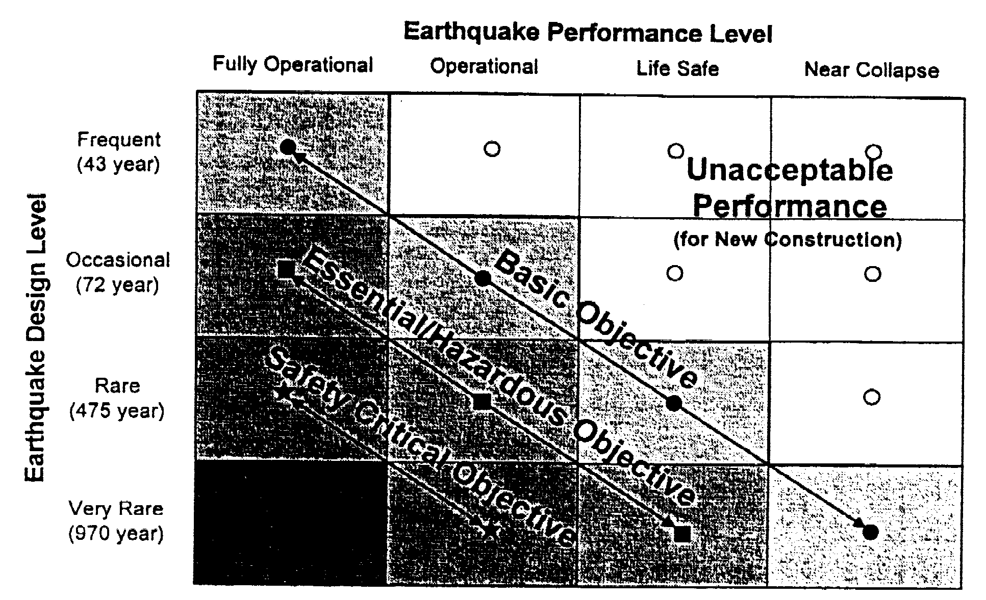 FIELD CHANGES. As
a result of non-documented changes and additions to existing buildings,
many more field changes are generally required for rehabilitation work
on existing buildings than for construction work on new ones, entailing
a need for clear, detailed drawings for the retrofitting of a building.
The construction must be monitored closely to ensure that the retrofitting
details and the intent of the retrofitting strategy are carried out --
thorough inspection is an integral part of any retrofitting project.
Figure 3. Recommended seismic performance design objectives for buildings [SEAOC 1995]
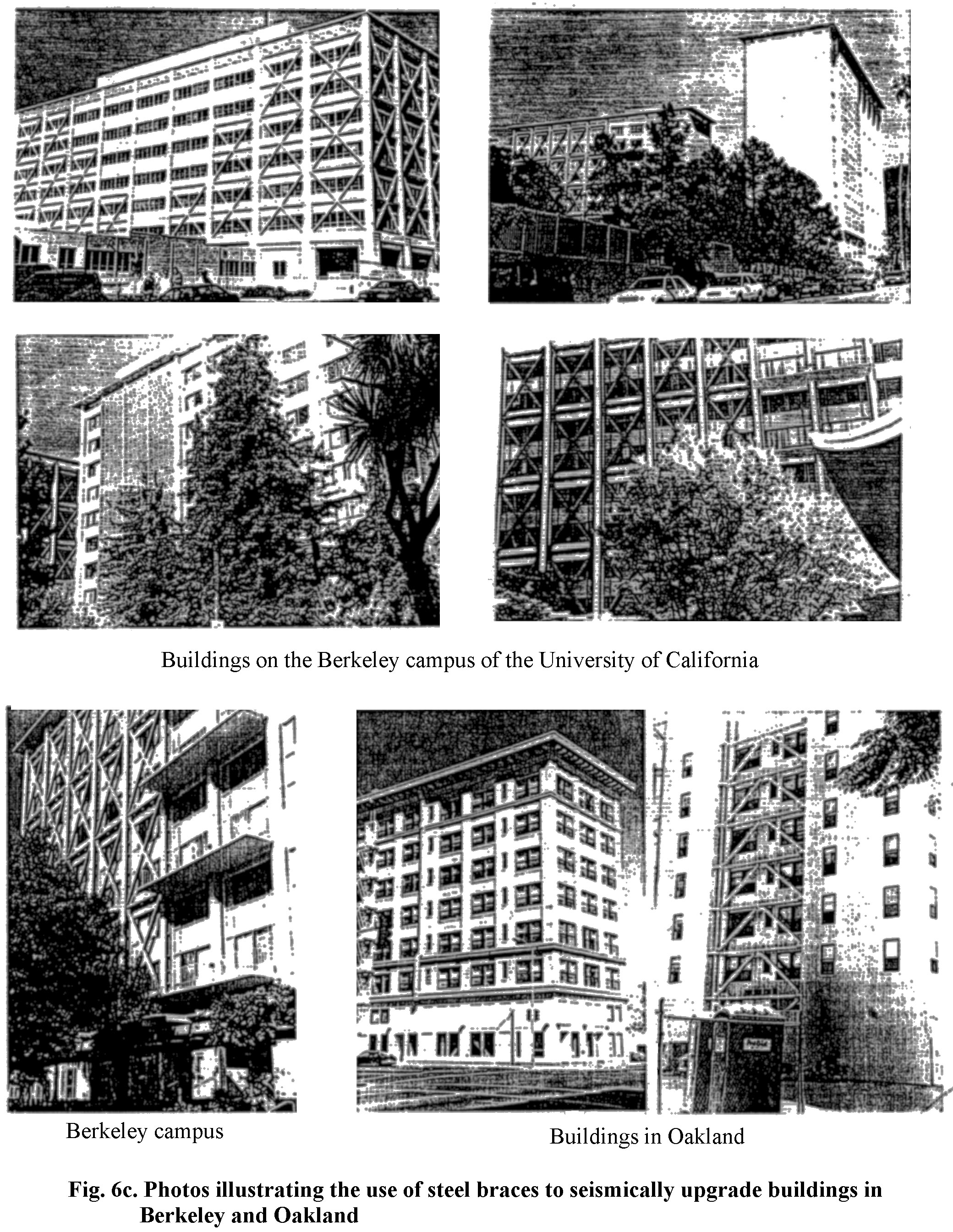
APPLICATION OF THE CONCEPTS AND GUIDELINES TO THE UPGRADING OF SOME EXISTING BUILDINGS The author and his research associates have conducted a series of detailed studies on the seismic upgrading of existing hazardous structures [Bertero & Whittaker, 1989; Miranda and Bertero, 1990; Miranda, 1991; Terán et al., 1995]. For a more detailed discussion of these studies, the reader is referred to the above references and to Bertero [1993]. Herein only the application to a few of the buildings studied will be summarized. In order to select an efficient strategy, the designer must begin by identifying the main response parameters which are unacceptable or inadequate and therefore need to be improved (have their values upgraded). These parameters are usually the following:
If some damage can be tolerated, then it is possible to dissipate some energy (ED) through plastic hysteretic behavior, by accepting a certain amount of EHm through the use of acceptable p. The designer, then, has at his or her disposal all of the above dynamic characteristics to play with -- V, K, x, T (K and M), and p. However, in order to use these tools it is necessary to have a clear picture of how the values of each of these dynamic characteristics affect the main response parameters, strength, deformation, energy dissipation, damage function or damage index, and acceleration and velocity. SEISMIC UPGRADING OF AN OLD RC FRAME BUILDING INFILLED WITH UNREINFORCED MASONRY WALLS USING POST-TENSIONED STEEL BRACES INTRODUCTORY REMARKS. Unreinforced masonry (URM) buildings and framed buildings infilled with URM walls and/or partitions, designed and constructed before the development and flourishing of seismic design, constitute an important part of the vast inventory of high-risk structures in most cities in regions of moderate to high seismicity. There is a need to develop technically and economically efficient retrofitting schemes to upgrade these buildings in such a way that they can have adequate performance during strong EQGMs. In recent years, several researchers and practitioners have shown that the seismic performance of existing buildings when subjected to strong EQGMs can be enhanced considerably by bracing the buildings with post-tensioned (PT) rods or cables. The use of this upgrading technique yields several advantages, such as versatility, low cost, fast and clean construction, and does not add any significant reactive mass to the existing facility. The implementation of this technique to the upgrading of framed buildings with URM infills will probably yield large economic advantages in the rehabilitation of these buildings. Nevertheless, there are many aspects and issues that need to be studied and resolved before attempting such implementation. Terán et al. [1995] have reported the studies conducted to shed light on the solutions of the above problems. The main objectives of the studies were: First, to identify, study and discuss relevant issues in the evaluation of the seismic hazards of non-ductile frames infilled with URM walls; second, to investigate the use of PT steel braces to reduce these seismic hazards in framed buildings with URM walls located in regions of high seismic risk in California; third, to study and discuss the issues that need to be considered during the design process to attain efficient (technically and economically) retrofitted facilities using this technique; fourth, to assess the use of this technique by studying the seismic performance of a specific building with non-ductile reinforced concrete (RC) frames and URM infills before and after it has been upgraded with PT braces; and fifth, to offer some conclusions drawn from the study and recommendations regarding the research that is needed to improve the application of such a technique. USE OF STEEL BRACES IN THE SEISMIC REHABILITATION OF EXISTING BUILDINGS. A review of the literature available on this subject reveals that the interest and the application of this rehabilitation technique have increased significantly in the last ten years. From this review, there is no doubt that the seismic rehabilitation or restructuring of an existing building using steel braces is an attractive option, and many different types of steel structural elements (members) and arrangements of these members can and have been used. Usually it is possible to achieve large increases in the lateral stiffness and strength of an existing building. The use of this technique offers the following advantages:
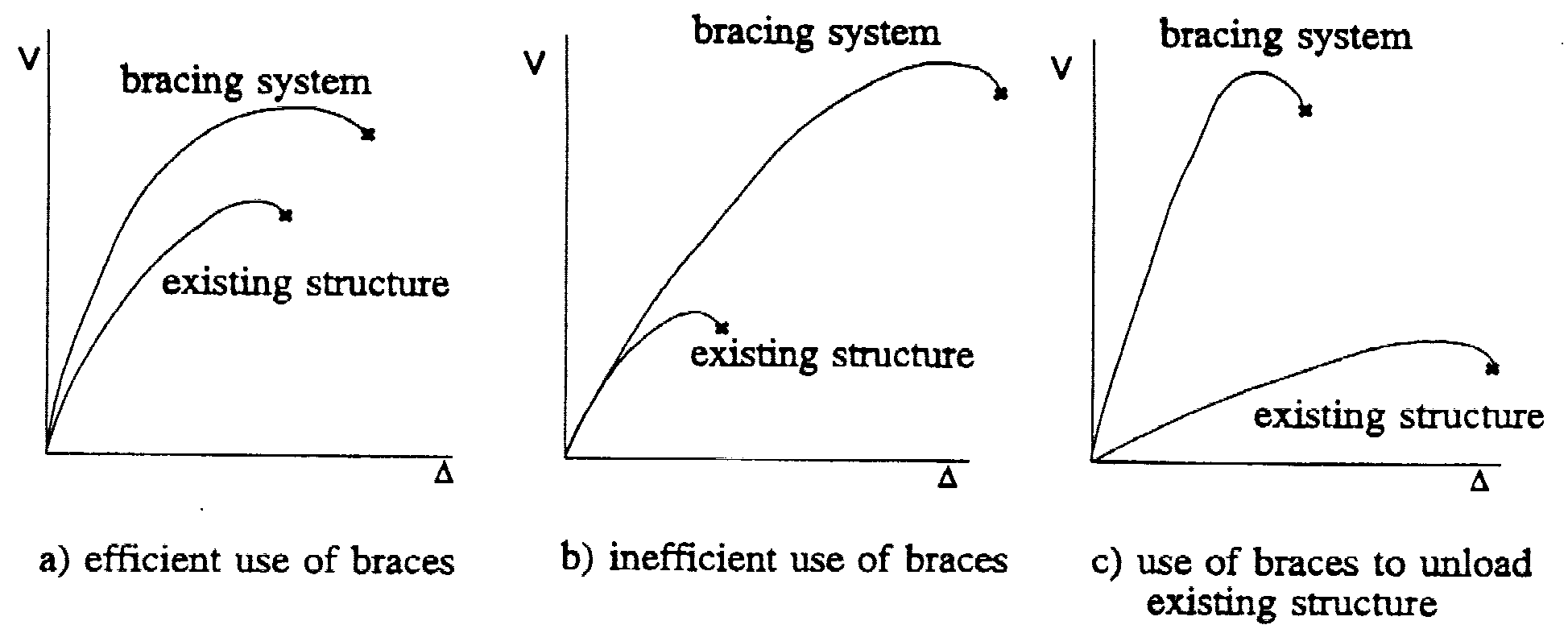
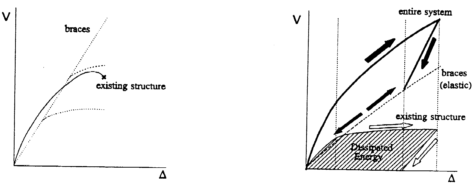
In this figure, the behavior of a one-story one-bay frame is qualitatively compared to the behavior of the same frame when it is braced. The comparison of strength demands on one end (top or bottom) of one of the columns of each of the two versions of the frame is shown in the same figure. As shown, an initial moment and an initial axial force (M0 and P0, respectively) exist in the column before lateral load is induced to the frame, Note that these initial forces usually are not the same in the bare and the braced versions of the frame. Once the frame is subjected to EQGM, there is a change in the moment and the axial force in the columns. As shown qualitatively, the moment variation is usually more significant than the variation of axial force in the bare frame, while the opposite can be said for the braced frame. In some cases, the change in behavior of the existing members helps to improve their seismic performance; nevertheless, an excessive increase in the axial forces (i.e., in tall slender buildings) can be detrimental to the members' performance. It is usually considered that the axial forces in the beams can be neglected in the design of the beams due to the presence of a slab that is rigid in its own plane, Nevertheless, if the forces in the braces are high, the axial force induced in the beam to equilibrate such force can be also high, and thus its effect should be assessed.
As pointed out above, the key issue for achieving good performance with these rehabilitating steel concentric bracing systems is the prevention of the overall (global) buckling of the braces. Thus, the design of the needed restructuring (retrofitting) usually has to be based on the sole criterion of avoidance of significant nonlinear elastic behavior of the braces and/or bracing system. As will be discussed later, most of the upgrading systems that are based on the use of energy dissipation devices require the use of structural steel bracing systems, which have to remain elastic even under the maximum credible or capable EQ ground motions (MCEQGMs). 
 Although the use of PT braces has advantages
and problems similar to the use of other types of steel braces, there are
some aspects peculiar to PT brace behavior.
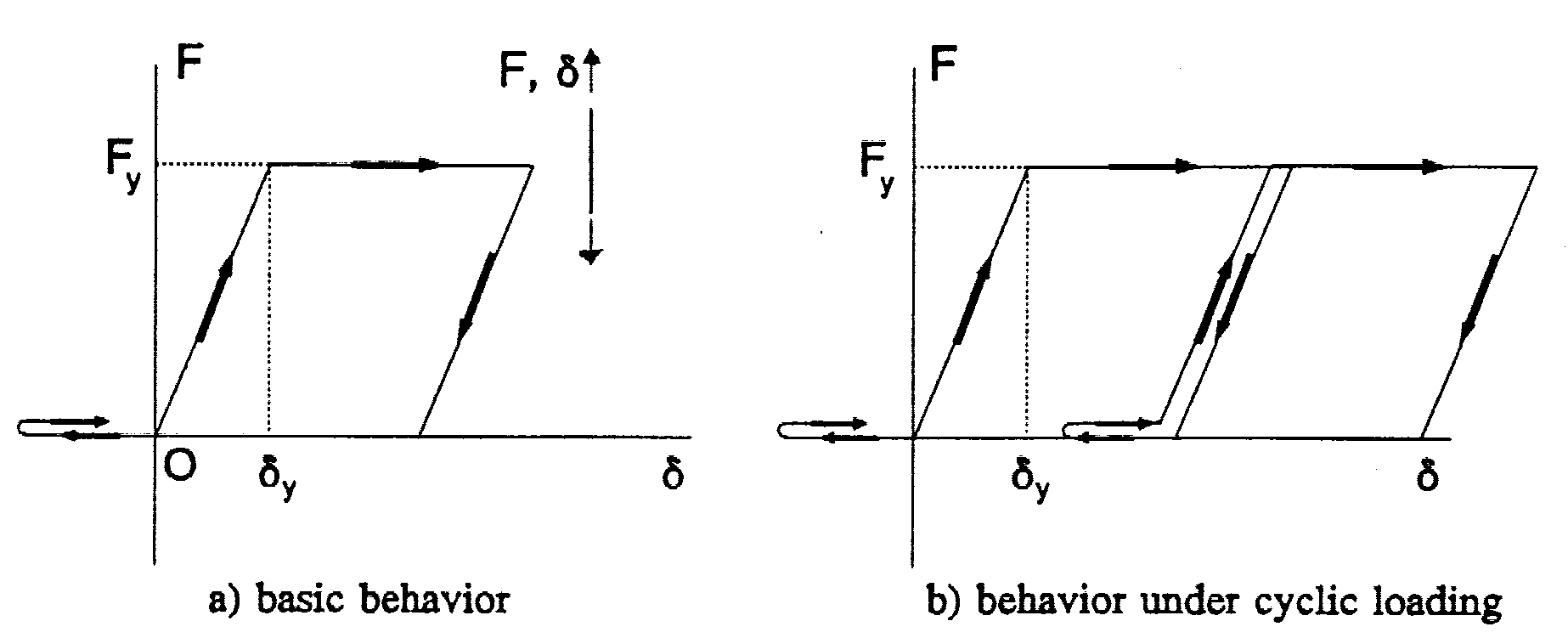
Figure 8a shows a counterpart
of Figure 7a for a prestressed rod or cable. As shown, both figures are
basically the same, with the exception that there is an initial state of
stress and strain (produced by the prestress) in the prestressed rod or
cable which is accounted for in Figure 8a by shifting the origin of the
axial force vs. axial displacement Cartesian axes. As a consequence, the
rod or cable can resist axial force under lateral forces that induce,
due to a decrease in the initial tension in the rod or cable, shortening
in the brace (this can be interpreted as the rod or cable developing a
compressive force), as shown in Figure 8a. From this figure, it is clear
that if the rod or cable loses its prestress, it loses its capacity to
resist
axial
loads when subjected to compressive strains. Figure 8b shows that if the
rod or cable yields, there is a loss of prestress. This is illustrated
by following the load path OABC in Fig. 8b. As shown, the rod or cable
remains elastic in the OA portion of this path. Once it reaches its yielding
strength (point A) it yields and follows AB. As soon as there is a load
reversal, the rod or cable unloads and reaches point C, which corresponds
to zero axial deformation. Comparison of the location 0 and C shows that
there has been a loss of prestress.
Figure 8. Axial displacement vs. axial load behavior of rod or cable with prestress [Terán et al., 1995]
The above observations can be used to understand the consequences that yielding of the PT braces can have on their performance. First, excessive loss of prestress will reduce significantly the ability of the PT braces to resist lateral loads that will shorten them. Second, excessive elongation of a PT brace can result in a decrease of the lateral stiffness of that brace. These two effects are detrimental to the performance of the PT bracing system. It is also convenient to assess the consequences of the PT braces' elastic behavior on the dynamic response of the structure. For example, if the braces carry the majority of the lateral loads, the structure will respond essentially elastically to the effects of an EQGM. Possible increases in the response of the entire building due to this effect should be carefully assessed.
Figure 10. Energy dissipation in existing buildings upgraded with PT braces.
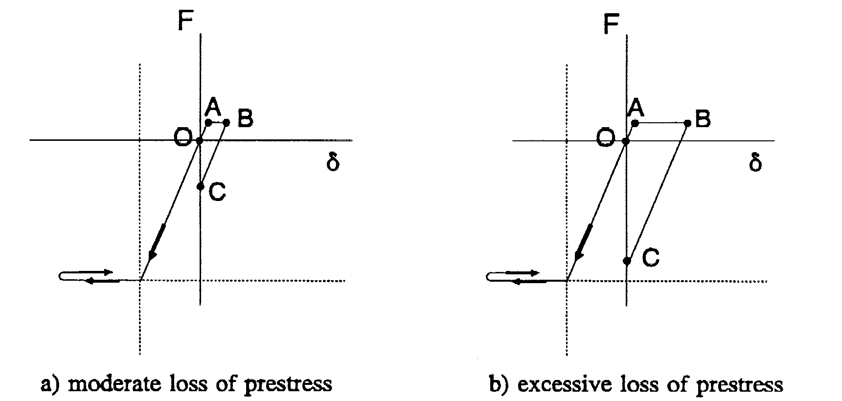
Figure 11. Axial displacement vs. axial load behavior of rod or cable with high prestress
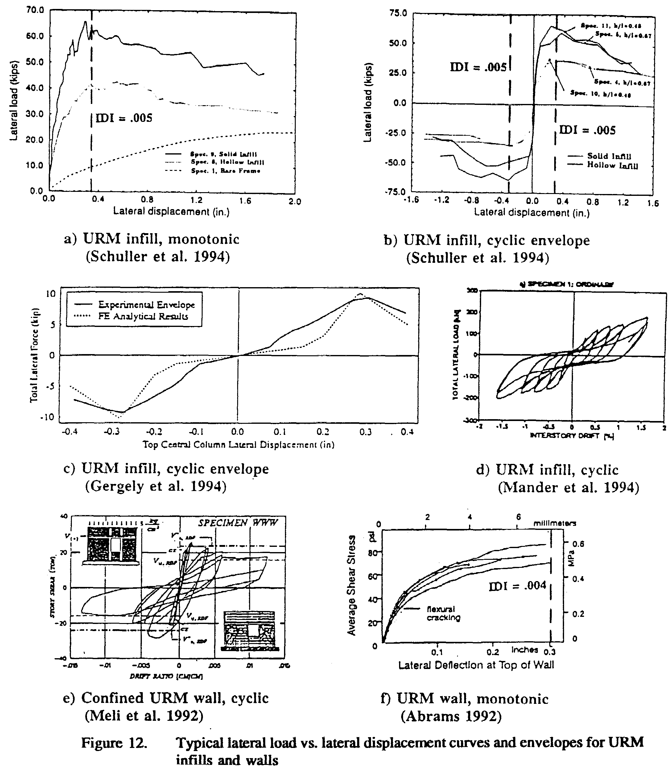
As illustrated in Fig. 12,
URM walls and infills show stable hysteretic behavior without considerable
degradation of their resistance and hysteretic energy dissipation capabilities
for relatively large drift. Thus, it seems that a reasonable way to enhance
the seismic performance of URM infills, and thus of the entire building,
consists in controlling their interstory distortions by controlling the
global lateral displacement of the building. Note that if the inplane degradation
of the mechanical characteristics of the URM infills is kept within reasonable
values, the probability of occurrence of an out-of-plane failure due to
in-plane effects diminishes considerably.
In some cases, damage control in URM infills cannot be achieved by only limiting their interstory distortions, given that in some cases the nonlinear cumulative demands are relevant to their behavior (damage). The fundamental period of translation (T) of low-rise buildings tends to be small, especially if they are infilled with URM walls and/or upgraded with a bracing system. In this range of T, the damage produced by nonlinear cumulative demands (such as the demand of hysteretic energy dissipation) is less relevant, in many cases, than that produced by interstory distortion [Terán-Gilmore, 1993]. In these cases, it is reasonable to attempt damage control by focusing on displacement control. For small T, one way to control the displacement of a structure is by decreasing its global ductility demands by increasing its lateral strength [Shimizaki, 1988; Qi and Moehle, 1991]. Nevertheless, once the lateral strength of the system reaches a certain value, a further increase in strength will not significantly affect the displacement response of that system. Thus, for the upgrading of a framed building with URM infills, it seems reasonable to increase adequately the strength and stiffness of the building through the introduction of the PT braces, in such a way that the interstory drifts, and thus damage in the URM infills, can be controlled to acceptable values (which must be defined as part of the performance criteria). Note that this is not the case for structures with larger T and built on soft soils, in which case the nonlinear cumulative demands can be significant and the elastic displacement can be similar to or even considerably larger than the inelastic displacement.
One of the drawbacks of keeping the frame members and PT braces elastic is the probable increase of the strength demand in the building when subjected to ground motion. One way of diminishing such demand is to provide energy dissipating devices to the structure. It should be noted that this is not necessary in the case of infilled frames, given that they have a large natural source of equivalent viscous and hysteretic energy dissipation ill the URM infills. Nevertheless, to use the URM infills as energy dissipators it is necessary to make sure they can provide this dissipation in a stable manner throughout the duration of its response to its critical ground motion. This is achievable by controlling their in-plane deformation by controlling the maximum IDI in the building, within certain limits.
To achieve the above performance criteria, the following philosophy is suggested:
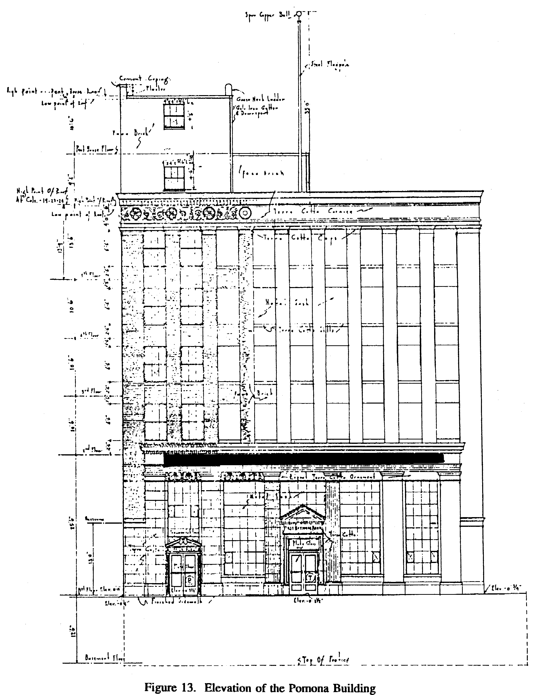
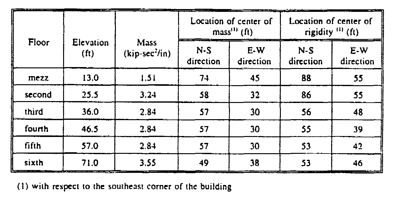
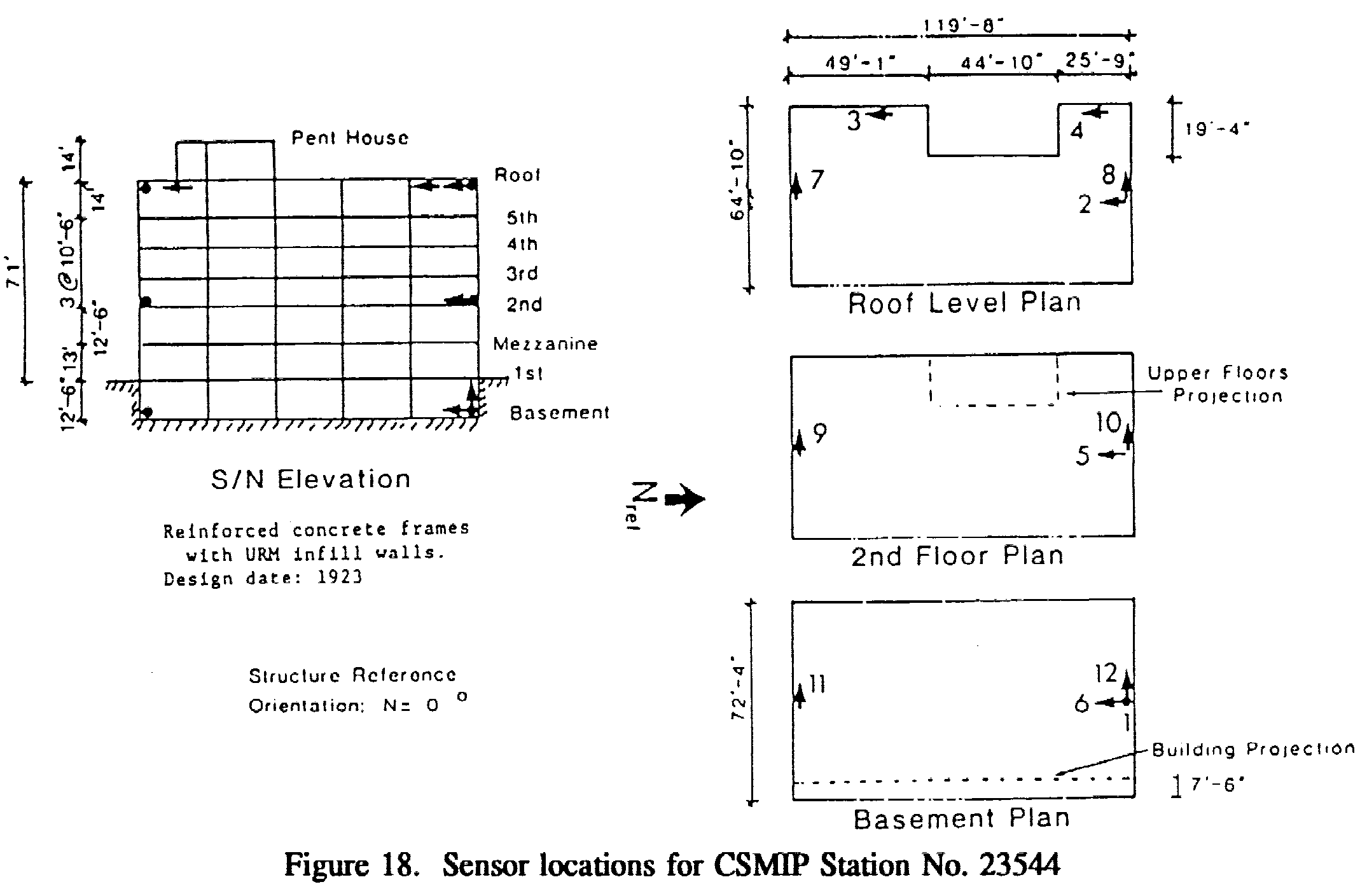
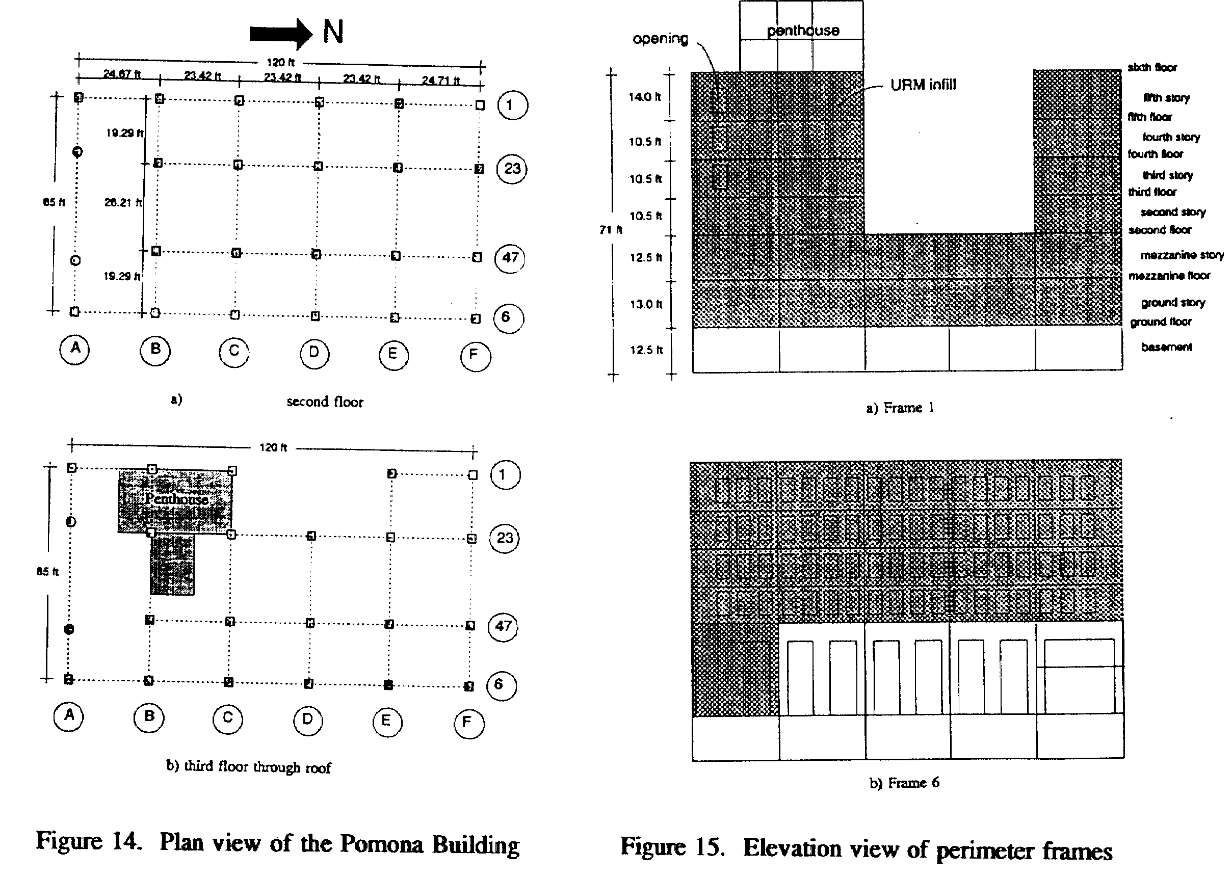 PRACTICAL APPLICATIONS. The technique of using PT braces to rehabilitate hazardous non-ductile RC frame buildings infilled with URM walls was applied to an old existing building identified herein as the Pomona Building. This building, illustrated in Fig. 13, is a six-story commercial building built in 1923, having as a structural system RC frames with unreinforced brick infills in all perimeter frames and three internal frames. At the ground level, the building measures 65 feet (E-W direction) by 120 feet (N-S direction) in plan, as shown in Fig. 14. Table 2 shows floor elevations and masses, along with the approximate locations in plan of the centers of mass and rigidity on each floor. The centers of mass corresponding to the second through fifth floors are close to the geometric centroid of the floor diaphragms, while large mass eccentricities exist in the mezzanine and sixth floors. In the mezzanine floor, the center of mass is displaced towards the northwest comer, and in the sixth floor (roof), towards the southwest corner. As shown in Table 2, the distance in the N-S direction between the centers of mass and stiffness in the mezzanine and second floors is very large, while in the third to sixth floors it is small. In the E-W direction, this distance is large for all floors. The floor system consists
of a three-inch thick one-way RC slab supported by RC joists spaced every
two feet, while the structural system for gravity and lateral loads is
formed by non-ductile RC frames (having beams, girders and columns) infilled
with URM walls. Figure 14 shows schematic plan views of the different floors
of the building, while Fig. 15 shows schematic elevation views of the four
perimeter frames and the notation used for floors and stories. As shown
in Fig. 15, there are URM infills in the perimeter frames, which probably
contribute significantly to resist the lateral loads induced in the building
by EQGMs. As shown, except for three small openings all infills in Frame
I are full infills (without openings), while those located in Frame 6 have
large openings, creating large stiffness and strength eccentricities in
the E-W direction of the building, especially in the mezzanine and second
floors (see Table 2). Infills located in the upper stories of Frames A
and F show similar characteristics (openings); nevertheless, in the lower
stories (ground and mezzanine) the stiffness and strength of Frame A are
lower than those of Frame F (by comparing Figs. 15c and 15d, it can be
seen that Frame A has a double-height first story and weaker and more flexible
URM infills in this story than those in Frame F), creating large strength
and stiffness eccentricities in these levels in the N-S direction (see
Table 2). This eccentricity (N-S direction) is magnified by the presence
of an L-shaped mezzanine (which, as shown schematically in Fig. 16, runs
along Frames 1 and F), and a large mass eccentricity at the roof in this
direction.
It can be concluded that the building has large irregularities
of mass, strength and stiffness in plan.
Table 2. Floor characteristics of the Pomona Building
As shown in Fig. 15, Frames A and 6, which correspond to the two facades facing the streets, show a double-height first level that has considerably fewer infills than the upper levels. As will be discussed in more detail later, this creates a weak and flexible first level, which produces a large irregularity in height, both in strength and stiffness. The basement of the building
is enclosed by a perimeter 12-inch thick concrete wall, which provides
a stiff and strong support for the columns of the ground story, except
those of Frame 6, because this perimeter wall has an offset of 7 feet 6
inches with respect to the plane defined by Frame 6, as shown in Fig. 17.
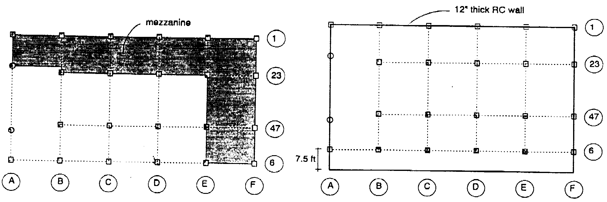
Figure 16. Plan view of mezzanine
Figure 17. Plan view of basement perimeter wall
Vulnerability Assessment
of the Pomona Building. This was done through 2D and 3D analyses of
linear elastic and nonlinear models of the building. Selection of some
of the structural parameters (dynamic characteristics) in the development
of these 2D and 3D models was guided and calibrated by the results of the
analyses of the recorded response of the building during the 1990 Upland
and 1992 Landers EQs. The building has been instrumented with sensors located
in the basement, at the second floor, and on the roof, as is illustrated
in Fig. 18. The dynamic characteristics of the existing buildings are shown
in Table 3.
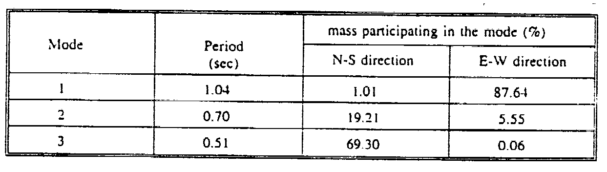
Table 3. Dynamic characteristics of Pomona Building from 3D elastic model
From analysis of the desired
performance of the building in the future and the levels of EQGMs that
can be expected at the site, it was decided that the seismic rehabilitation
of this Pomona Building should be based on the minimum or basic design
performance objectives of the performance-based EQ-RD matrix shown in Fig.
3. Further-more, an analysis of expected EQGMs at the site and their return
period indicates that the preliminary design would be controlled by the
life safety performance level. From an analysis of the expected EQGMs at
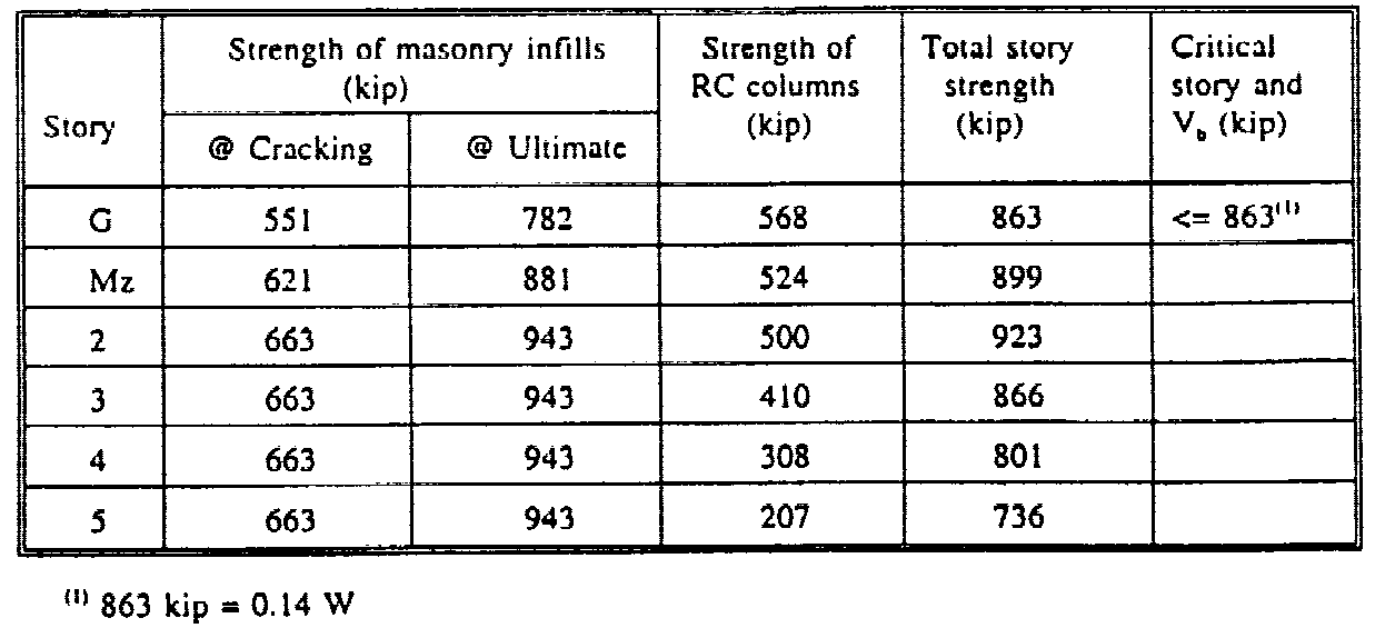
the site, the spectra shown in Fig. 19 were selected for the vulnerability
assessment of the life safety of the existing building as well as for its
rehabilitation. According to the selected design performance objectives,
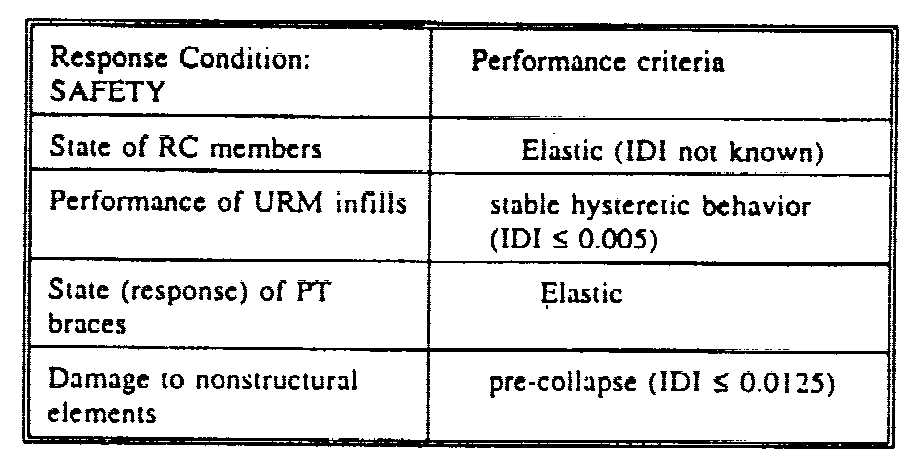
the life safety design criteria summarized in Table 4 were formulated.
Table 4. Safety limit
state design criteria
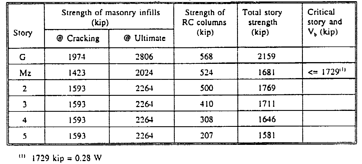
Table 5. Estimated ultimate story strength in the N-S direction
Table 6. Estimated ultimate story strength in the E-W direction
From the results obtained
in the analyses conducted on the existing buildings, it was concluded that
"the
existing building is not satisfying the desired performance of life safety
and that under the very rare but possible maximum credible EQ (MCEQ) it
could collapse."
The estimated maximum (ultimate) story shear strengths
of the existing building are shown in Tables 5 and 6 and plotted in the
spectra shown in Fig. 19.
"The building exhibited insufficient lateral
strength and stiffness as well as large irregularities of mass, lateral
stiffness, and strength through plan and height. "
Figure 19. Design Spectra for Safety
Design of the Post Tensioned Bracing System Selection of layout
of bracing system. An ideal solution is to place the PT braces
in
the
perimeter of the building, However, aside from the structural properties
of the bracing system, probably the most important consideration needed
to determine its final layout is related to the architectonic and functional
integrity of the building. These types of considerations significantly
influenced the proposed layout of the PT bracing system. It should be mentioned
that it was virtually impossible not to alter the existing distribution
of space within the building.
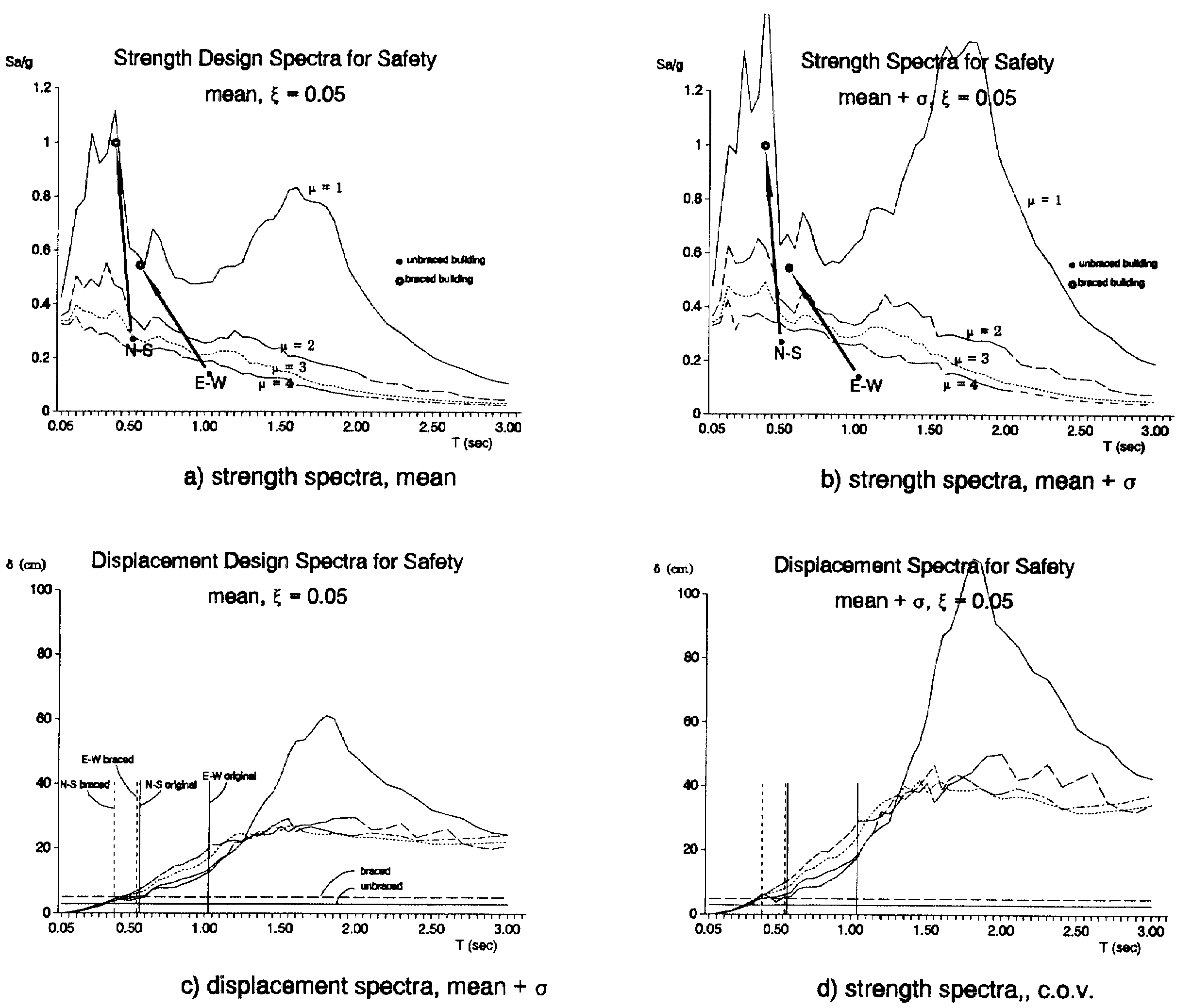
Figure 20 shows the proposed location in plan of the PT braces, while Figures 21a to 21e show schematically the location in height. The properties and geometry
of what were considered the best two alternatives for the PT bracing system
are summarized in Tables 7 to 9 and Figs. 20 and 21. As shown in Fig. 21,
the first option (configuration 1) consists in adding braces to four planes
of resistance: 23 and 47 in the N-S direction, and C and E in the E-W direction;
while the second option (configuration 2) consists in adding to the previous
four planes one more plane of resistance in the E-W direction (one more
braced bay located in Frame B). An asymmetric distribution of braces
in the planes of resistance parallel to the N-S direction was provided
to correct the large torsional response of the building when loaded in
this direction. Each diagonal in Fig. 21 represents two braces, which were
provided in this way as to avoid inducing large load eccentricity to the
existing elements. As shown, each brace spans two stories in order to achieve
angles that allow for an efficient solution. Five different types of braces
were considered, as shown in Tables 7 to 9. As shown, the sizes of the
braces in the lower two stories are considerably larger than those in the
upper four stories, in such a way as to avoid the existence of a flexible
and weak first story. The diameter of the PT-braces ranged
from 2 1/8" to 3 1/2", and it was proposed to use galvanized bridge wire
with a yielding stress of 150 ksi. Fifty per cent of the available yielding
stress is used for post-tensioning.
Table 7. Characteristics of proposed bracing system for configuration 1, N-S direction 
Table 8. Characteristics
of proposed bracing system for configuration 1, E-W direction
Table 9. Sizes of PT braces
In the proposed upgrading configurations there is a need to strengthen some existing columns in such a way that they can resist adequately the increase in axial loads induced in them by the braces, particularly those columns that support braces in both directions, such as those in the intersection of the following frames: 23 and C, 23 and E, 47 and B, and 47 and E. Figures 21c and 21d illustrate the need to add new beams to frames C and E in such a way that the braces have enough support at the floor levels (i.e., to avoid the buckling of the slab). Table 10 summarizes the dynamic characteristics
of the first translational modes estimated from the stick models corresponding
to the E-W and N-S directions.
Table 10. Dynamic properties of stick model of upgraded building
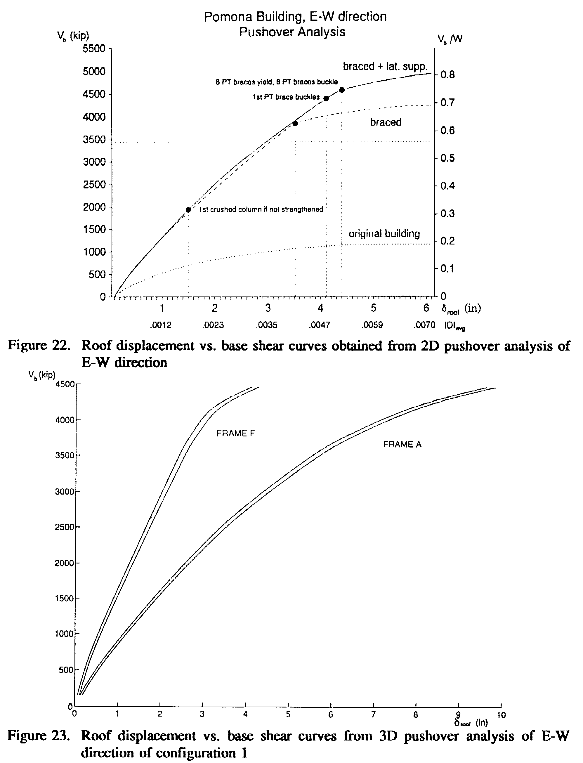
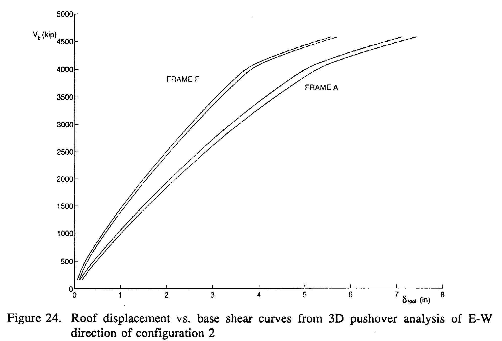
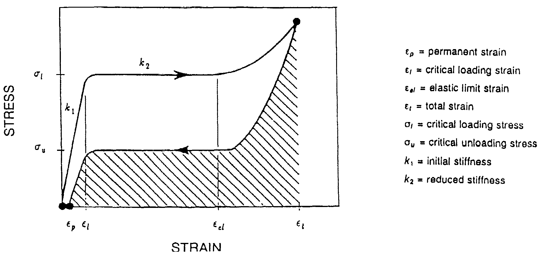
Figures 19a and c illustrate the lateral strength of the building upgraded with brace configuration I (obtained by adding the strength of the original building plus that provided by the PT braces) relative to the design strength spectra for the safety limit state. As shown, in the N-S direction, the building is expected to dissipate some energy (p slightly larger than 1). As mentioned before, this energy dissipation should be provided by the URM infills. The values of the elastic coefficients of distortion (which is defined as the ratio between the maximum-n and the average IDI demands in the building) in plan and height in both directions were reduced considerable by the introduction of the PIT braces: from about three for both directions in the original building to 1.5 and 1.6 in the E-W and N-S directions, respectively. From Fig. 19a it can be concluded that "the designed bracing system enhances considerably the performance in both directions, and this performance can be considered within the target performance for safety that has been specified in the selected design criteria" (Table 4). The performance of the rehabilitated building was assessed through a series of 2D and 3D linear elastic and nonlinear analyses. The curves shown in Fig. 22 permit comparison of the performance of the rehabilitated building with that of the original building. It is clear that the lateral stiffness and strength of the Pomona Building are considerably enhanced by upgrading it with PT braces. Figure 23 shows four droof vs. Vb curves, one for each corner of the building upgraded with brace configuration 1, obtained from a 3D pushover analysis in the E-W direction. It is clear from these curves that there is a significant torsional response when this version of the upgraded building is loaded in the E-W direction. As shown, the comers located in the south end of the building (Frame A) have a droof demand that is roughly twice that corresponding to the corners located in the north end (Frame F). It can be observed that the difference between the droof demands of the south and north comers tends to increase with increasing droof. To improve the torsional performance
of the rehabilitated building, a new layout of PT braces was selected and
designed. This new layout was a modification of configuration 2 (shown
in Fig. 20), in which the braced bays in Frame E of brace configuration
1 has been translated to frame B. Thus, the modified configuration 1 has
the same number of braced bays as configuration 1. Figure 24 shows the
results from a 3D pushover analysis in the E-W direction for the modified
configuration 2. Comparing the results (curves) presented in this figure
with those plotted in Fig. 23 for configuration 1, it can be concluded
that the torsional responses of the upgraded building with the modified
configuration 2 is reduced considerably. As shown in Fig. 24, the
droof
demands in the corners located in the south end of the building (Frame
A) are now roughly 1.3 times the droof
demands corresponding to the corners located in the north end (Frame F)
and this ratio remains fairly constant with increasing droof.
Concluding Remarks.
In view of the above apparent weakness
in the use of just post-tensioned steel bracing systems, efforts have lately
been devoted to searching for ways of overcoming this weakness. Analysis
of the available ways of dissipating energy through the use of energy dissipation
devices have permitted identification of a possible technical solution
for such weakness, and this is the use of the Shape Memory Alloys (SMAs).
This is so because these alloys have the ability to "yield" repeatedly
and not lose their prestress, as is illustrated in Fig. 25. From analysis
of the experimental results obtained at EERC [Sazaki, 1989; ; Aiken et
al., 1993; and Clark et al., 1995], it is clear that the use of post-tensioned
Nitinol (also written as NiTi, a nickel-titanium alloy) rods can be technically
a very attractive solution, because as a consequence of its energy-dissipating
capacity it can lead to a great reduction in the main response parameters
(acceleration, relative displacement, and interstory drift) of the frame
to which it is attached when it is subjected to earthquake ground motions.
However, this ideal technical solution, because of its present high cost,
will not be an economical solution. A technically and economically feasible
solution appears to be the use of post-tensioned high-strength steel rods,
together with what can be called a self-balanced prestressed energy dissipation
device based on the use of SMAS.
Fig. 25. Idealized stress-strain relationship of Nitinol alloy [Aiken et al., 1993]
INNOVATIVE TECHNIQUES FOR THE SEISMIC UPGRADING OF EXISTING FACILITIES INTRODUCTORY REMARKS. As discussed previously, the significant life and economic losses induced by recent earthquakes clearly indicate a need to control damage to our civil engineering facilities not only under rare major earthquake ground motions but also under the occasional moderate and even the frequent minor earthquake ground motions. For buildings, damage control is needed to protect not only entire structural systems, but also their nonstructural components, equipment, contents and service lines, under the different levels of earthquake ground motions, This protection can be achieved using different types of "Protective Systems." Herein, only the following two types of protective systems will be briefly discussed and illustrated: Base Isolation and Passive Energy Dissipation Systems. BASE ISOLATION. The notes prepared by Kelly [1994a and 1994b], Aiken [1994b] and Kircher [1994] discuss in detail the concepts of base isolation, linear theory and design, the different types of isolation systems, applications, future directions in base isolation, and the seismic isolation code provisions. In what follows, after summarizing the concept of base isolation and its advantages compared with other protective systems, the different base isolation systems, applications for upgrading buildings and the observed responses are briefly described. The Concept of Base Isolation. The traditional idea was to prevent ground motions from being transmitted from the building foundation into the superstructure. At present, the basic idea is to control the earthquake energy input into the building and so to reduce its response to acceptable levels of deformation and rate of deformation. When a building is built on an isolation system, it should have a fundamental frequency that is lower than both its fixed-base frequency and the dominant frequencies of the ground motion. The first mode of the isolated structure then involves deformation only in the isolation system, the structure above being almost rigid. The higher modes that produce deformation in the structure are orthogonal to the first mode, so that if there is high energy in the ground motion at the higher mode frequencies, this energy cannot be imparted to the structure. In this way, the demand on the structural system is reduced, as are the accelerations transmitted to the internal nonstructural components and equipment. This makes isolation a very attractive approach where protection of expensive sensitive equipment is needed, and it is no surprise that this technology has been used for buildings such as hospitals, computer centers, emergency operations centers and nuclear facilities. The beneficial effects of the isolation system are independent of damping, although some damping is desirable to suppress resonance due to long-period motion, but high levels of damping are not needed in isolation systems for buildings where protection of internal equipment is the goal of the design. High levels of energy dissipation lead to smaller displacements in the isolation system but higher accelerations in the superstructure, and are thus advantageous for bridges, where control of displacements is important and accelerations in the deck are not important. Advantages of Seismic Isolation Base Isolation vs. Traditional Fixed-Base Approach to Earthquake-Resistant Design and Construction. In the conventional fixed-base design approach, improvement of the seismic response of a building was attempted by increasing strength (which usually increased the stiffness). Lately, emphasis has shifted away from increase in strength to increase in stiffness, following the recognition that damage is more a consequence of deformations and deformation rates than of strength. However, in buildings located on rock or firm soils the resulting increase in stiffness (directly or through the increase in strength) results in buildings with shorter periods of vibration, which leads to the development of larger accelerations in the structures and in its nonstructural components and contents. In few words, a fixed-base building tends to amplify the ground motion. To minimize this amplification, the structural system must either be extremely rigid or have a large amount of damping. At best, rigidity results in the contents of the building experiencing the peak ground accelerations, which may still be too high for sensitive internal equipment and contents. Incorporating high levels of damping in a structural system means either damage to the system or designing an expensive structural form to mitigate this damage. Base Isolation vs. Passive Energy Dissipation Approach. As will be discussed later, significant advances have been made in recent years, improving the seismic performance of structures through the use of energy dissipation devices. However, the use of these devices is still in its infancy in the U.S. Usually, the proper use of these devices demands an increase in the stiffness of the structures, which may result in a significant increase in the accelerations developed in the structure and in the contents of the building, which, as discussed above, may lead to problems in the case of sensitive equipment and contents. Base Isolation Systems. Several types of isolation systems are currently in use, and several others are being developed or investigated. Despite wide variations in the detailing of the base isolators, their system behavior, and the design, the systems can be divided into the following two distinctive basic groups (Chopra 1995).
Theory and Design. Kelly [1994b] and Chopra [1995] discuss elementary linear dynamic analysis that permits insight into the dynamic behavior of isolated buildings. Civil Applications of Base Isolation. Over the past decade, the use of seismic isolation around the world has proliferated. Kelly [1994a] and Aiken [1994b] discuss this application in different countries. Table 12 summarizes and compares
the status in 1986 and 1993 of base-isolated buildings worldwide. Only
applications of base isolation in the United States and Japan will be summarized
herein.
Table 12. Status of base isolation worldwide: buildings [Aiken 1994]
Base Isolation in the United States.
At
present, there are many base-isolated building projects
in the U.S. Some of these projects are for new
structures
but a large number are seismic retrofit projects (Table 13). These
retrofit projects were stimulated by damage to several historic buildings
in San Francisco, Oakland and surrounding areas from the 1989 Loma Prieta
EQ. As pointed out by Kelly [1994a], it is interesting to note that to
date the use of isolation for new buildings is mainly in Southern California,
whereas most isolation projects in Northern California are for retrofit.
The photos of Fig. 26 illustrate some of the buildings that have been or
are being upgraded in the San Francisco Bay Area using base isolation.
Table 13. Retrofit base-isolated buildings and projects in the United States [Aiken 1994]
Base Isolation in Japan. At present the most widespread use of this innovative protective approach is in Japan. The first building project was approved in 1985 and since then the implementation of base isolation in Japan has been rapid. As of January 1993, the total number of base-isolated buildings was 67, and as of January 1995 the number exceeded 75. Most of these isolated buildings are in the Tokyo area and comprise a wide range of building types. Most have reinforced concrete superstructures and are up to six stories. Only a few base-isolated buildings exceed six stories, and these have a composite steel-reinforced concrete structural system. As of January 1993, there were only three base-isolated wooden-framed structures. Roughly half of the buildings have natural rubber (low damping) isolators with additional damping components, such as steel bars or frictional elements. Most of the other half of isolated buildings use lead-rubber bearings and high-damping rubber bearings. Applications of sliding systems are rare. All rubber isolators in Japan up to 1994 were circular and most about 40 to 60 cm in diameter. The smallest isolators in use are 20 cm diameter bearings under a two-story wooden houses and the largest are 1.5 meter diameter bearings. The isolation periods at large displacements cluster around 2.5 seconds, although there are some few isolated buildings with periods greater than 3.0 seconds Low-Cost Isolation Systems. As pointed out before, the emphasis in most base isolation applications up to this time has been on large structures with sensitive or expensive contents, but there is increasing interest in the possibility of applying the technology to public housing and other buildings such as schools and local health centers in developing countries. Several projects are under way for such applications. A challenge in this type of application is to develop a low-cost isolation system that can be used in conjunction with vernacular methods of construction, such as masonry block and lightly reinforced concrete frames. Demonstration buildings for housing projects have been complete using high-damping rubber bearings as the isolation system in Santiago, Chile [Sarrazin and Moroni, 1992] and in Squillace in Southern Italy [Vestroni et al. 1992]. A demonstration project in Indonesia is currently under construction. Both of these projects have partial support from the United Nations Industrial Development Organization. Response of Base-Isolated Buildings During Recent Earthquakes Response to the Ground Motions Generated by the 1994 Northridge Earthquake. When the Northridge earthquake occurred, there were in the greater Los Angeles area five occupied base-isolated buildings and several others in various states of design and construction. Two are supported on elastomeric isolators -- the University of Southern California (USC) Teaching Hospital and the Los Angeles County Fire Command and Control Facility (FCCF) -- while thesprings and viscous dashpots. These three buildings were isolated during their construction, i.e., they were not isolated for seismic upgrading. The USC Hospital, an eight-story steel-braced frame structure built in 1988, is the base-isolated building closest to the epicenter. The steel-braced frames are supported on 68 lead-rubber isolators and 81 elastomeric isolators. The peak free-filed ground acceleration was 0.49g, and the peak acceleration at the foundation was 0.37g. The peak accelerations in the structure above the isolators were 0.13g and 0.2lg at the base and the roof, respectively, implying amplification ratios of 0.32 and 0.57 relative to the input motion at the foundation level. These ratios are in the expected range for a seismically isolated structure under the level of recorded ground acceleration. No structural damage was observed, and the hospital remained completely functional during and after the EQ. There were no reports of damage to equipment. Pharmacy shelves, files and bookshelves retained their contents. An adjacent new USC building, of the same height but on a fixed base, suffered significant nonstructural damage and virtually all the shelf contents in the pharmacy fell. The FCCF building has as a structural system a two-story braced-steel frame supported on 32 high-damping rubber isolator. While the recorded response in the north-south direction was as expected for a PGA of 0.18g at the foundation, with amplification ratios of about 0.4 and 0.5 at the first floor and roof, respectively, the recorded response in the east-west direction was unexpected, with spike representing amplification ratios substantially greater than 1.0. A field inspection of the facility revealed that an architectural detail at the east-facing entryway near the north wall of the building may have restrained the relative movement of the ground floor with respect to the foundation. The original tiles were damaged during the 1992 Landers EQ, and the replacement tiles apparently were stronger and provided more lateral restraint at the ground floor demonstrating the importance of proper maintenance and repair of buildings. The third base-isolated facility consists of two identical three-story braced-steel frame residences in Santa Monica, each supported at its comers by GERB helical springs and viscous dashpots. Additional springs are distributed around the building perimeter. From inspection of these buildings, it appears that this isolation system is more effective vertically than horizontally, because several details limit horizontal movement. Damage was observed as a consequence of this restrained movement. Response to the Ground Motions Generated by the 1995 Great Hanshin (Kobe) Earthquake. Although there has not been any retrofitted building in which base-isolation was used when this EQ occurred, there are two recently completed buildings in the northern part of Kobe near the city of Sanda that were moderately shaken by the Kobe EQ. One of these is a very large six-story building having a composite steel-reinforced concrete superstructure with a total floor area of 505,000 ft² (47,000 m²) . The other, on a site approximately one-third of a mile (500 m) away, is a three-story reinforced concrete laboratory with a total floor area of 5200 square feet (486 square meters). These structures are supported on relatively stiff soil approximately 22 miles (35 km) northeast of the epicenter of the earthquake, and because of their proximity to one another, it can be assumed that both experienced similar levels of ground motion. The smaller of the two structures is part of the Technical Research Institute of the Matsumara-Gumi Construction Company. it was completed in March 1994 and is used as a laboratory and conference area. The superstructure is a reinforced concrete space frame with a total height of 42 ft (12.8 in) and is supported on eight high-damping rubber bearings. The fixed-base period of the superstructure is 0.24 second and the target period of the isolation system vanes with displacement from 1.2 seconds at 0.5 inch (1.35 cm) to 2.3 seconds at 8.0 inches (20.3 cm). Adjacent to the isolated structure is a four-story steel moment frame with a rigid foundation, and the two buildings are connected via sliding joints. The peak ground accelerations observed
at the Matsumura-Gumi site were approximately 0.27g in both the longitudinal
and transverse directions of the building, with a duration of strong motion
of approximately seven seconds. Although digital data is not yet available,
Table 14 shows the peak response accelerations, indicating that while there
was some attenuation of the input, it was not as great as anticipated
for this level of excitation. There was no damage in the isolated structure,
but at the roof of the adjacent fixed-base structure there were reports
of dropped ceiling tiles and a crack in a ventilation duct. The accelerations
at the roof of this steel frame peaked at 0.98g. Based on scratches in
the stainless steel sliding joint at the first floor of the isolated building,
the relative bearing displacement was almost five inches (12.5 cm), which
would imply a vibration period of approximately two seconds, However, the
measured period was closer to 1.5 seconds, perhaps because the EQ struck
early in the morning when the temperature in the basement of the building
was about O° C (32° F), causing a slight stiffening of the rubber
isolators.
The larger building is the West Japan Postal
Services Computer Center, which is owned by the Ministry of Post and Telecommunications
and serves as the computer center for all the financial transactions of
this Ministry in western Japan. It was occupied in late 1994, and since
that time has been closed to the public for security reasons. The lateral
force-resisting system in the superstructure consists of braced frames
while the isolation system is a hybrid of several different types of devices
including 54 lead-rubber bearings, 66 natural rubber bearings, and 44 steel
coil dampers. The fixed-base period of the superstructure is 0.68 second,
and the target period of the isolation system varies with displacement
from 2.8 seconds at 4.7 inches (12 cm) to 3.3 seconds at 9,4 inches (24
cm). Although detailed records of the response of this building to the
Kobe EQ are not yet available, peak response quantities have been reported
(Table 15). These data indicate that the isolation system was very effective.
The input accelerations can be assumed to be equivalent to those at the
Matsumura-Gumi site, but the bearings in the Postal Center are not exposed
to the environment. The peak displacement of the isolators in this building
was reported to be approximately four inches (10 cm).
Table 15. Floor accelerations in the West Japan Postal Center
USE OF PASSIVE ENERGY DISSIPATION SYSTEMS FOR EARTHQUAKE PROTECTION. Although since the late 1960s there has been a growing interest in the use of mechanical energy dissipation devices to reduce the dynamic response of buildings to extreme load conditions, such as those caused by wind storms, and EQs, it was in the early 1980s when the interest in the development and application of these devices for EQ-RD and EQ-RC became a reality through significant analytical and experimental investigations. This perhaps occurred due to a contemporaneous tremendous growth in the interest of developing and applying energy approach to EQ-RD. From analysis of the basic balanced energy equation (Eq. 3), it is clear that there are two ways of dissipating part of the input energy: one is through the hysteric behavior of the structural material as a consequence of its inelastic (yielding in the case of metallic material) deformation, EHm .; and the other is through the hysteretic viscous or equivalent viscous damping of the structure, EHx . Therefore, from the analysis of this energy equation and the way that it can be obtained, i.e., by integrating the equation of motion of an elastic/inelastic system, it is clear that there is an essential physical difference between the dissipation of energy through yielding of the metals, i.e., EHm ., and that through equivalent viscous damping, EHx . While dissipation of energy due to equivalent viscous damping occurs even in the elastic behavior of the structural material, the dissipation due to plastic deformation (yielding) is not present during the elastic response of the structural material. Thus, from this physical point of view it is unfortunate that in the literature the devices that have been developed and used to achieve these two basic different ways of dissipating energy has been denominated under the general term "passive damping devices". Numerous pseudo-dynamic and earthquake simulator studies accompanied and augmented by analytical investigations have been conducted in the last decade. The last few years have seen the beginning of implementation of these devices in buildings to control their seismic response, as well as effort devoted to developing code provisions for passive energy dissipating systems by the SEAONC and by the Building Seismic Safety Council (BSSC). In spite of these efforts, as will be discussed in more detail later, although at present there are many proposed projects, to date there are only very few seismic applications of passive energy dissipation devices in buildings in California, and these few have been for seismic upgrading purposes and as a consequence of the observed response during the 1989 Loma Prieta earthquake. However, there have been several other applications to buildings in other countries as will be pointed out later. In this paper, attempts will be made to give a general overview of the main types of passive damping devices, which offer some potential for their use in buildings (new and existing) to control their seismic responses, and that have been the focus of research and development activities in the last decade. Analysis and Design Issues. The main issues have been discussed by Whittaker [1994]. Types, Behavior and Applications of Energy Dissipation Devices. According to Aiken [1994a], the main types or systems can be classified under the following groups: Friction, Metallic, Lead Extrusion, Shape Memory Alloys, and Viscous and Viscoelastic.
Friction devices made by Sumitomo Metal
Industries, Ltd. (Fig. 27b) have been used in two buildings in Japan [Aiken
and Kelly, 1990], and a friction device manufactured by Pall Dynamics,
Ltd., has been used in three buildings in Canada, one retrofit and two
new buildings [Pall et al., 1987, 1991; Vezina et al., 1992]. The Pall
device (Fig. 28) is intended to be mounted in X-bracing. Several earthquake
simulator studies of multi-story steel frames incorporating Pall devices
have been performed [Filiatrault and Cherry, 1987; Aiken et al, 1988],
and a design methodology has been developed for friction-damped structures
Simpler devices with Coulomb behavior include those which use a brake pad material on steel friction interface [Giacchetti et al., 1989; Tyler, 1985]. Other friction schemes that involve no special devices, but rather allow slip in bolted connections, have also been developed [Roik et al., 1988; Fitzgerald et al., 1989]. A promising refinement of the slotted bolted concept has recently been made using a brass on steel friction couple [Grigorian et al., 1992]. Earthquake simulator tests of a three-story steel building model with these slotted bolted connections (SBC) energy dissipators have been completed. Tests on full-scale beam-to-column connections of steel SMRFs have recently been completed successfully [Popov, 19951. 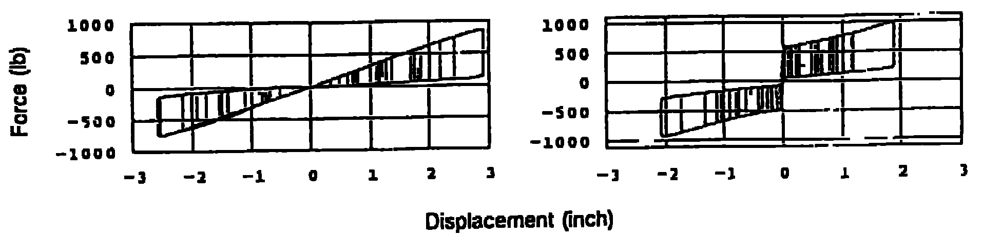
Figure 29. Fluor-Daniel EDR hysteresis loops [Richter, 1990]
Issues o importance with friction devices are long-term reliability and maintenance; the potential for introduction of higher frequencies as the devices undergo stick-slip behavior; and possible permanent offsets after an earthquake. The maintenance and protection from deterioration of a device in which the sliding surfaces are required to slip at a specific load during an earthquake, even after decades of nonuse, is essential.
One device that uses X-shaped steel plates is the Bechtel Added Damping and Stiffness (ADAS) device. ADAS elements are an evolution of an earlier use of X-plates, as damping supports for piping systems [Stiemer et al., 1981]. Extensive experimental studies have investigated the behavior of individual ADAS elements and structural systems incorporating ADAS elements [Bergman and Goel, 1987; Whittaker et al., 1991]. The tests showed stable hysteretic performance (Fig. 30). 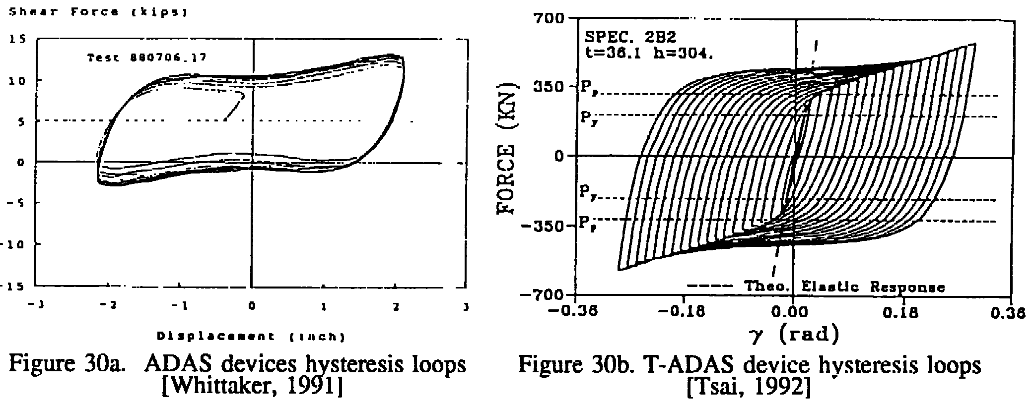
The principal characteristics which
affect the behavior of an ADAS device are its elastic Stiffness, yield
strength and yield displacement. ADAS devices are usually mounted as part
of a bracing system, which must be substantially stiffer than the surrounding
structure. The introduction of such a heavy bracing system into a structure
may be prohibitive.
For the retrofit of this building, the design team and their client, Wells Fargo Bank, chose a higher performance criterion than that called for in the Uniform Building Code -- one that included some measure of damage control. The client wished to be able to resume banking operations shortly after a major earthquake. The design team established several design objectives in order to attain this performance goal. These objectives included: limiting the lateral forces in the building during the design-level earthquake so as not to overload the existing foundations; and, limiting the maximum roof deflections during the design-level earthquake to approximately those deflections experienced during the Loma Prieta earthquake. 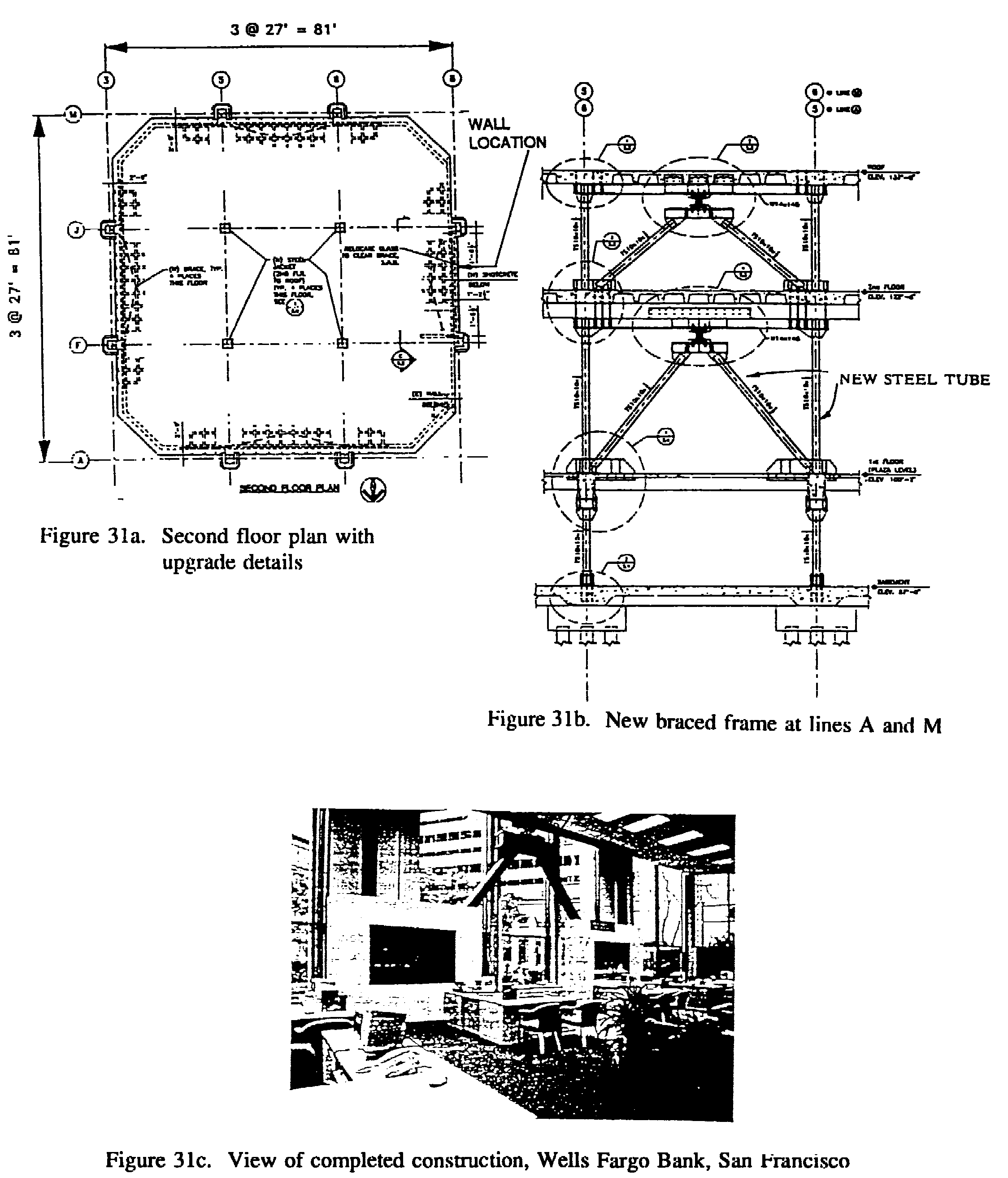
The design-level strong ground motion at the site was characterized using two response spectra: one site-specific with a peak ground acceleration of 0.39g, the second a generic spectrum for a soft soil site with a peak ground acceleration of 0.459. Acceleration time-history records compatible with both spectra were developed. The solution chosen by the team involved the use of ADAS steel energy dissipation devices mounted atop chevron bracing assemblies and arranged around the perimeter of the building. Three and four energy dissipation devices were added in the first and second stories, respectively. The seven identical ADAS elements consisted of 1.5-inch thick, 9-inch high 50 ksi steel plates. The retrofitted building was analyzed using linear, equivalent linear and nonlinear techniques. 3D response spectrum analyses were used to estimate the response of the building during the Loma Prieta EQ. Equivalent linear analysis was then used to assess the viability of the proposed retrofit scheme and to size the chevron braces and ADAS elements. 2D nonlinear time-history analyses of the frames incorporating ADAS elements, using the spectrum-compatible ground motions, were undertaken to confirm the forces and deformations in both the existing reinforced concrete element and the new chevron brace/ADAS element assemblies. The nonlinear analyses demonstrated that the deformations in the upgraded building under the design-level EQ were acceptable, and that the desired level of damage control could be achieved through the use of energy dissipation devices. It was shown that adding energy dissipators substantially reduced the response of the two-story reinforced concrete building.
Several types of mild steel energy dissipators have been developed in Japan [Kajima Corporation, 1991; Kobori et al., 1988]. So-called honeycomb dampers have been incorporated in 15-story and 29-story buildings in Tokyo. Honeycomb dampers are X-plates (either single plates or multiple plates connected side by side) that are loaded in the plane of the X. (This is orthogonal to the loading direction of triangular or ADAS X-plates). Kajima Corporation has also developed two types of omni-directional loading steel dampers, called "Bell" dampers and "Tsudumi" dampers [Kobori et al., 1988]. The Bell damper is a single-tapered steel tube, and the Tsudumi dampers is a double-tapered tube intended to deform in the same manner as an ADAS X-plate but in multiple directions. Bell dampers have been used in a massive 1600-ft ski-slope structure to permit differential movement between four dissimilar parts of the structure under seismic loading while dissipating energy. Both of these applications are located in the Tokyo area. Another type of joint damper for application
between two buildings has been developed [Sakurai et al., 1992]. The device
is a short lead tube that is loaded to deform in shear (Fig.32). Experimental
investigations and an analytical study have been undertaken.
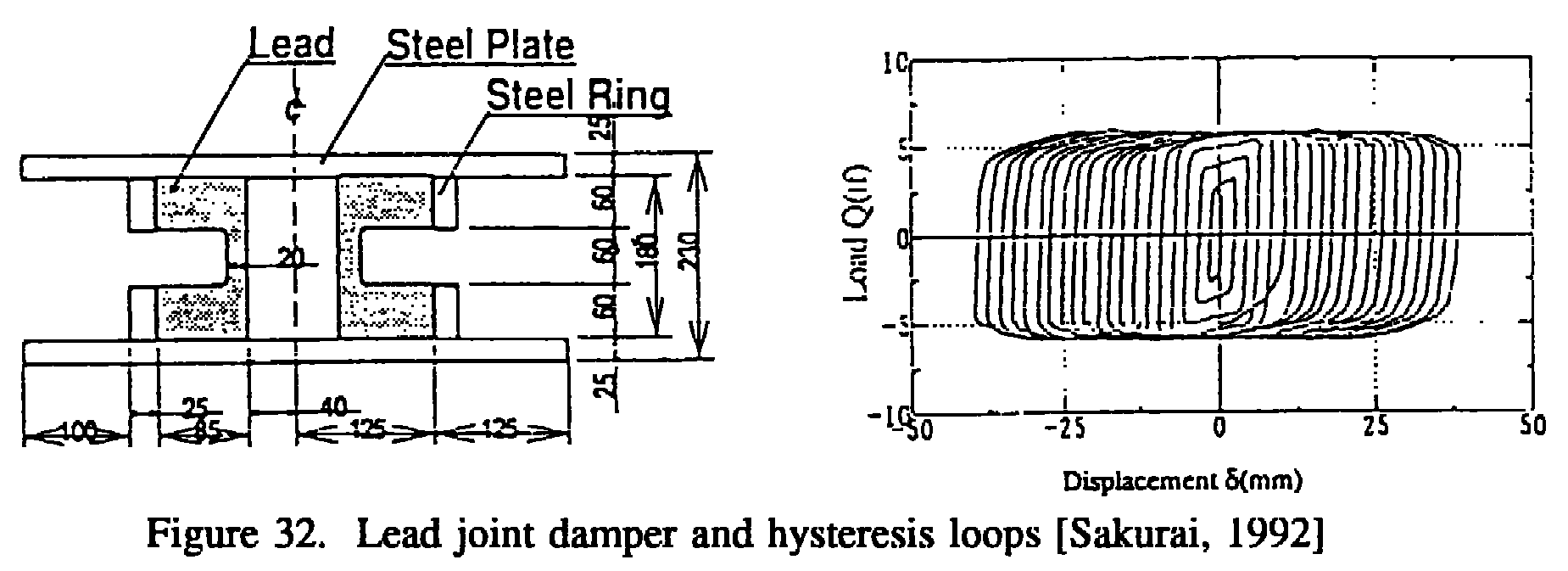
LEDs have a number of particularly desirable features: their load-deformation relationship is stable and repeatable, being largely unaffected by the number of loading cycles; they are insensitive to environmental factors; and tests have demonstrated insignificant aging effects [Robinson and Cousins, 1987].
Several earthquake simulator studies of structures with SMA energy dissipators have been carried out. At the Earthquake Engineering Research Center (EERC) at the University of California [Aiken et al., 1992; and Clark et al., 1995], a three-story steel model was tested with Nitinol (nickel-titanium) tension devices as part of a cross-bracing system, and at the National Center for Earthquake Engineering Research [Witting and Cozzarelly, 1992], a five-story steel model was tested with copper-zinc-aluminum SMA devices. In this second study, devices with torsion, bending and axial deformation modes were investigated. Typical hysteresis loops from these tests are shown in Fig. 34. Results showed that the SMA dissipators were effective in reducing the seismic responses of the models. At present at EERC application of SMAs to the repair and/or upgrading of the connections of existing steel special moment-resisting frames (SMRFs), as well as to the design of new steel and precast reinforced concrete structures, is under investigation. Although these SMAs are very expensive relative to steel, it is believed that their use in the connections or in the construction of structural fuses to control the response of these SMRFs can be technically and economically very efficient when compared to other current solutions.
Figure 34. NiTi (Tension) and Cu-An-Al (Torsion) hysteresis loops [Aiken, 1992; Witting, 1992]
Several companies in Japan have developed damping systems based on different VE materials. Shimizu Corp. has developed a bitumen rubber compound (BRC) VE damper which has been used in one 24-story steel building of a twin-tower complex. Both buildings are instrumented to proved seismic response data for comparison between VE-damped and undamped responses [Yokota et al., 1992]. Bridgestone Corp. has developed a visco-plastic rubber shear damper, and this has been shake-table tested in a five-story steel frame model [Fujita et al., 1991].
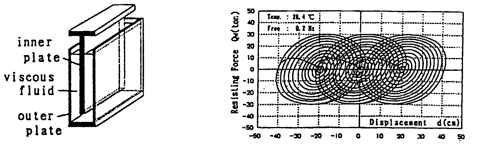
Figure 35, VD wall and hysteresis loops [Miyazaki, 1992]
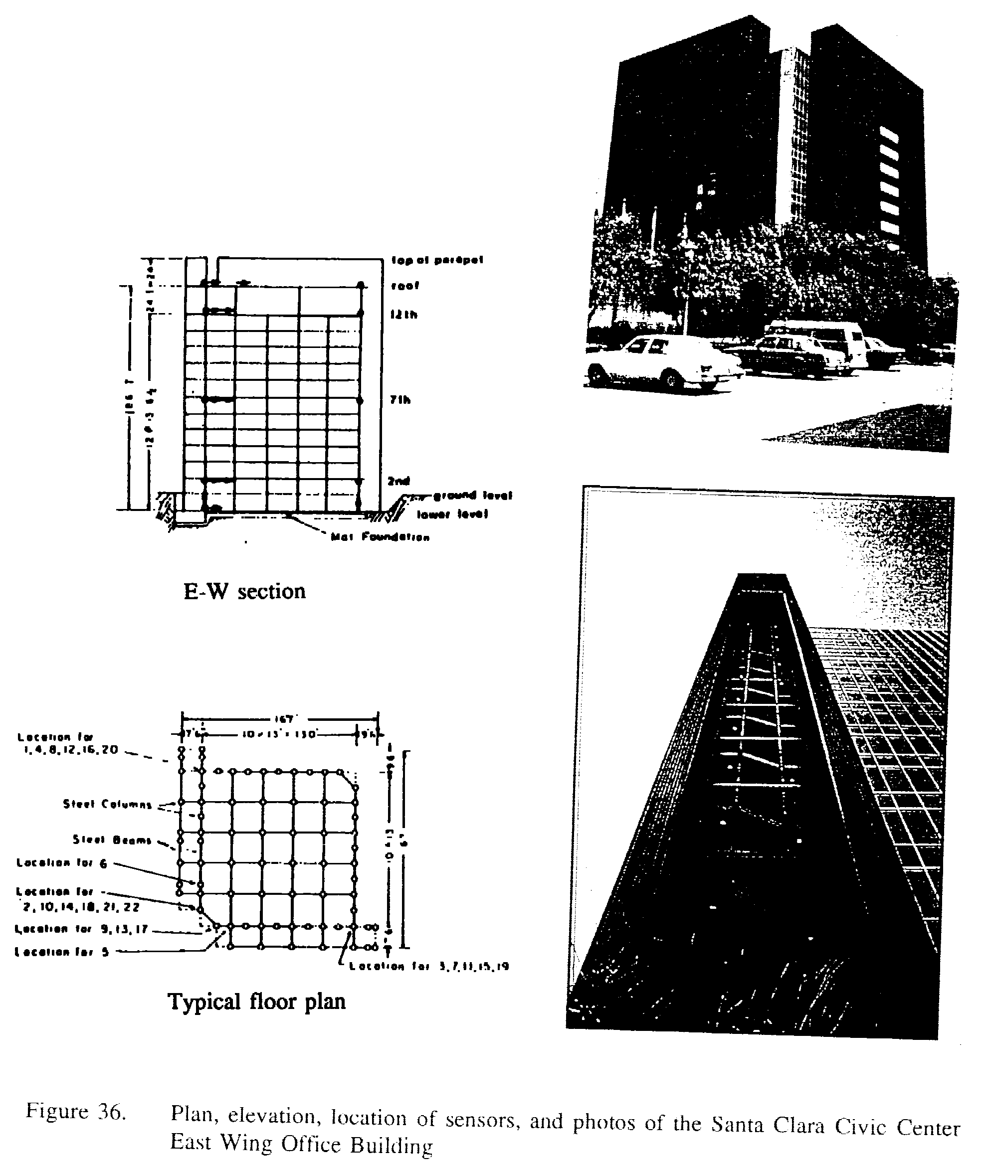
The building is instrumented with 22 accelerometers, which have provided valuable data on the response of the structure in a number of earthquakes. This data has been the basis of a number of studies of the building [Boroschek and Mahin, 1991]. Of particular interest in these investigations has been the intense and long duration of response of the building to even moderate ground motions and the role of torsional coupling in the recorded responses. The equivalent viscous damping in the fundamental mode was found to be less than 1% of critical. With only a few exceptions, the design of the existing building meets all the requirements of the 1988 Uniform Building Code. As part of the retrofit, the Crosby Group was charged to investigate the earthquake response data obtained from the building and to review the structural plans and calculations. Three strong motion records were the focus of the study: the Morgan Hill earthquake of April 24, 1984 (M = 6.2), the Mt. Lewis earthquake of March 31, 1986 (M= 5.8), and the October 17, 1989 Loma Prieta earthquake (M = 7.1). The peak accelerations recorded for these earthquakes, at the basement level of the building were 4%, 4% and 11%, respectively. The building amplified the ground motions (at the roof level) to 17%, 32% and 36%, respectively. Of particular interest is the 4% to 32% (8 times) amplification in the Mt. Lewis event. Three different types of energy dissipators were initially considered by the design team. These included (a) the steel-yielding ADAS device; (b) the friction-slip energy dissipating restraint; and (c) the 3M viscoelastic shear damper. The viscoelastic dampers proved to be best suited for this application since they provided the building with significant damping for frequent, low-level earthquake shaking, as well as for larger events. Trial damper sizes were selected on the basis of simplified design procedures similar to those prescribed in the SEAONC and NEHRP documents. The preliminary design incorporated four dampers per building face per story level (Fig. 37). However the preliminary damper configuration presented occupancy problems to the County. The County eventually determined that only two dampers on each building face at each floor level would be accepted. This solution, although not optimal, nonetheless increased the equivalent viscous damping in the fundamental building mode to about 17% of critical, providing substantial reductions in building response for all levels of earthquake shaking. A finite element model of the building was then developed in the SADSAP environment [Wilson, 1993] and analyzed using ground motions similar to those described above. These analyses confirmed that significant reductions in building response would be realized through the addition of the viscoelastic shear dampers. As part of the device design program, dynamic
tests of two large dampers have recently been perfomed [Blondet, 1993].
The objectives of the tests were to demonstrate that the dampers had the
capability to withstand the strain levels expected to occur under extreme
earthquake conditions and to verify the mechanical properties of the viscoelastic
material used in the dampers. The dampers were subjected to both harmonic
and earthquakes loading. A range of harmonic excitations were applied to
the devices to evaluate the material storage and loss moduli (G' and G")
dependencies on temperature, frequency, and amplitude of loading. The earthquake
loading signals corresponded to response time histories obtained from computer
analyses of the building containing the dampers, subjected to the service-level
earthquake, design-level earthquake and the Maximum Credible Earthquake
(MCE). To evaluate the adequacy of the connection detail as well as any
other problems that could be encountered in the installation of these dampers,
one damper was fabricated and installed first. Figure 38 illustrates some
details of the dampers used.
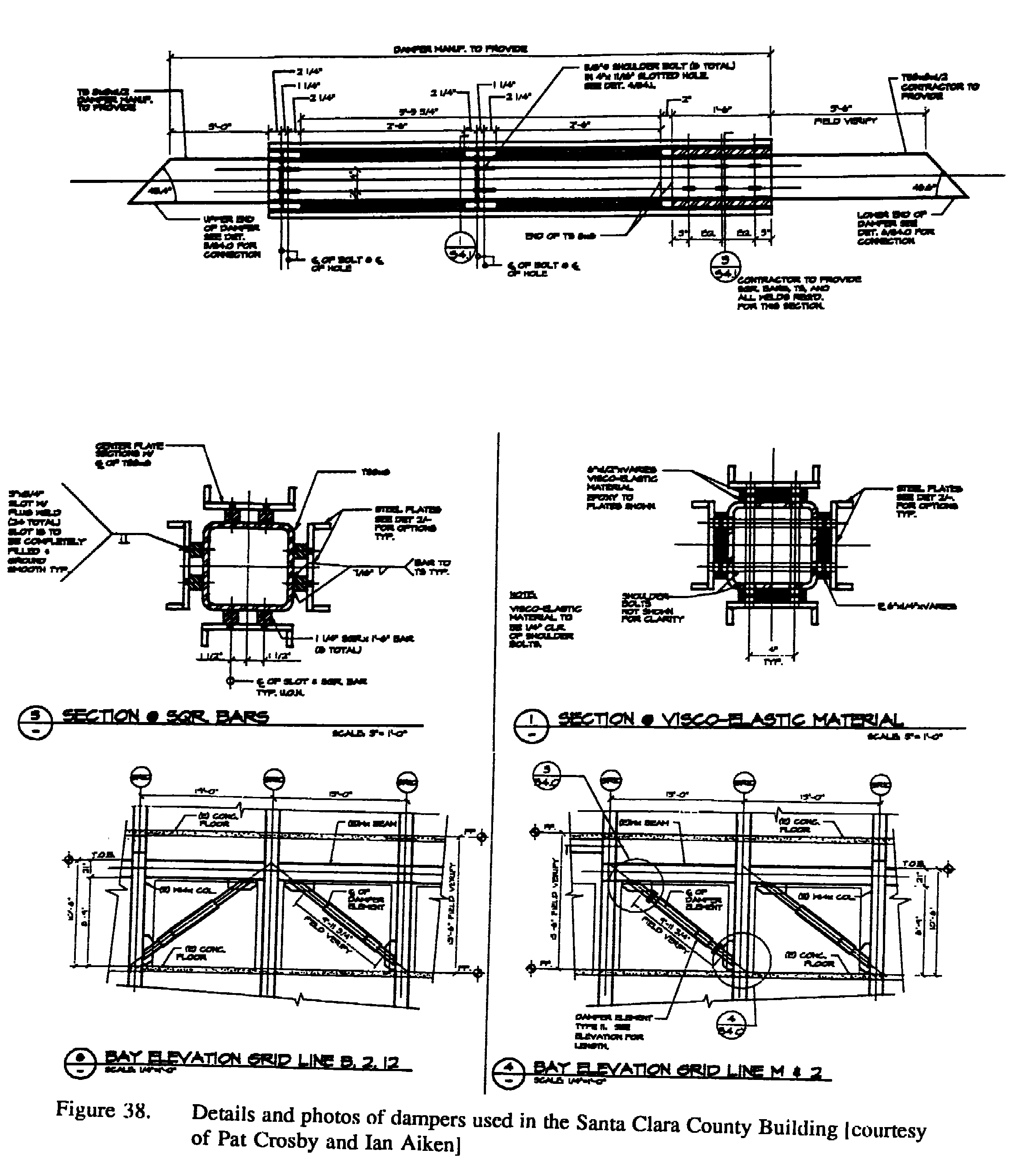
The design team led by Cole/Yee/Schubert (CYS) were charged with analyzing the building for compliance with current seismic provisions and with assessing the likely performance of the building in the event of the design-level earthquake. It was concluded that although the building complied with the strength requirements of the 1970 Uniform Building Code (the code that was used as the basis for the seismic upgrade work in 1984), the detailing of the critical components and connections was inadequate, and that further upgrade work was required. The maximum strength of the existing building was computed to be approximately only 20% of the reactive weight of the building. A number of retrofit strategies were considered. New reinforced concrete structural walls and supplemental steel bracing systems were two conventional solutions investigated by CYS. Both of these structural solutions had a significant impact on the ongoing occupation of the building, and both involved substantial construction work at all levels of the building, especially in the basement. The design team also considered two innovative solutions for the retrofit of this building: seismic isolation and supplemental damping. A seismic isolation solution was studied in some detail, but nonstructural issues precluded its implementation. A supplemental damping, or energy dissipation solution, was then investigated. The existing building has fundamental translational periods of approximately 0.75 seconds in both directions. The peak of the site-specific spectrum coincides with the fundamental period of the building. Viscous, viscoelastic, yielding and functional
hysteretic energy dissipation systems were considered. The preliminary
analyses were undertaken assuming the use of linear viscous dampers such
as those described below. A linear viscous damping solution was selected
for two reasons: (a) the forces in the energy dissipators would be out
of phase with the forces in the existing nonductile reinforced concrete
elements; and (b) the energy dissipators would be effective for a wide
range of earthquake intensity, thereby providing the building with enhanced
damage control for more frequent minor moderate earthquake shakings.
Taylor Devices' fluid viscous dampers have been tested by Constantinou at the State University of New York at Buffalo [Constantinou et al., 1993]. A typical fluid damper consists of a stainless steel piston with bronze orifice head and an accumulator and is filled with silicon oil. The piston head utilizes specially-shaped passages which alter the flow characteristics with fluid speed so that the force output is proportional to the fluid velocity raised to the power a , where a is a predetermined coefficient in the range of 0.5 to 2. A design with a equal to 1.0 results in a linear viscous damper. The characteristics of the Taylor fluid viscous dampers were confirmed through the earthquake simulator testing of a three-story model structure [Constantinou et al., 1993]. The experimental results demonstrated reductions of drift and shear force of the order of two to three in comparison to the response of the model without dampers, for a wide range earthquake input motions. Of note is the fact that the dampers had no effect on the stiffness of the structure while increasing its energy dissipation capacity. According to the mathematical model, the addition of linear viscous energy dissipation devices to the building significantly reduced the forces and deformations during the design-level earthquake and by limiting the base shear force to approximately 0.20W, only limited strengthening work will be required in the superstructure. Additionally, by limiting the interstory drifts to acceptable levels, CYS hoped to eliminate the need to upgrade critical nonductile components.
The Provisions provide general design guidelines applicable to a wide range of possible energy dissipation devices rather than addressing specific methods of energy dissipation. By remaining general, the Provisions rely on mandatory testing of system hardware to confirm the engineering parameters used in the design and to verify the adequacy of the energy dissipation systems. Some systems may not be capable of demonstrating acceptability by test and consequently would not be permitted. The performance goals that form the basis of the Provisions are identical to those of conventional structures, that is, to prevent substantial loss of life by partial or complete building collapse in the design-level earthquake. No special protection against structural on nonstructural damage is sought or implied by the Provisions. Exposure of energy dissipation devices to environmental effects that include wind-induced member actions, aging effects, high- and low-cycle fatigue, changes in operating temperature, exposure to airborne contaminants and moisture, may lead to either degradation or changes in their mechanical characteristics. Such effects must be accounted for in the design process. SUMMARY, CONCLUSIONS AND FUTURE DIRECTIONS IN UPGRADING BUILDINGS USING PROTECTIVE SYSTEMS
Many of the completed base-isolated new buildings, as well as some few of the retrofitted buildings, have experienced earthquakes, and so far their performance has been predicted. With the exception of the USC Medical Center in the 1994 Northridge earthquake, the earthquakes, if close, have been small or have been moderate and distant so that the accelerations experienced have not been large. As more new isolated buildings are built and existing buildings are retrofitted using base isolation techniques in earthquake-prone regions of the world, we can anticipate learning more about the behavior of such structures and it will be possible to reduce the degree of conservatism that is currently present in the design of these systems and structures. It should be possible to bring about an alignment of the codes for fixed-base and isolated structures and have a common code based on the specified level of seismic hazard and structural performance and in this way allow the economic use of this new technology for those building types for which it is appropriate. As is stated by Kelly [1994], it is clear that the use of seismic isolation has finally achieved a level of acceptance that will ensure its continued use and its further development and that this new and radical approach to seismic design will be able to provide safer buildings at little additional cost as compared to conventional design. Additionally, base isolation may play a major role in the future in projects as diverse as advanced nuclear reactors and public housing in developing countries.
As the number of viable energy dissipation
systems increases, it is becoming increasingly necessary to find a common
basis for evaluation and comparison of these systems, and their use in
established reasonable design standards. There have been few test programs
which have included more than two or three systems, and those have not
attempted comparisons beyond evaluation of general performance characteristics.
The following conclusions have been formulated by Aiken [1994] on the basis
of the available information.
2. The design coefficient for added damping building systems can be selected using the reduction factor, rf. This requires that both the fraction of critical damping assumed for the design spectra and the equivalent viscous damping assumed for the design spectra and the equivalent viscous damping provided by the energy dissipation system be known. 3. The relative effectiveness of damping decreases as the amount provided increases. The cost-effective limit for an energy dissipation approach will depend on the structural system and the type of damping device selected. 4. There is a need to consolidate the basis
for subsequent developments and applications of seismic energy dissipation
systems. Some of the current general and specific issues related to these
future applications are.
(b) Variable performance characteristics as a function of loading, e.g., temperature, amplitude and frequency dependence (c) Practical design methodologies and criteria (d) Long-term reliability, e.g., deterioration, corrosion, design life (e) Maintenance requirements and in situ performance evaluation (f) Standards for device assessment and comparison CONCLUSIONS AND RECOMMENDATIONS CONCLUSIONS. From the studies summarized above, the following conclusions can be made.
In the U.S., the use of fluid VD, which
has been used for many years in the military and aerospace fields, are
now being used in seismic structural engineering. They are relatively insensitive
to temperature changes, and can be very compact in size in comparison to
force capacity and stroke.
Most of the studies on seismic vulnerability assessment of existing facilities and on the development of guidelines for seismic upgrading of existing buildings were sponsored by the National Science Foundation. Experiments conducted on the use of the post-tensioned steel rods were supported by a research grant from Mr. Rioboó and the experiments on the ADAS elements by a research grant from Bechtel. All of these supports are gratefully acknowledged. The author wishes to thank his ex-graduate students, I. Aiken, L. J. Alonso, M. Blondet, E. Fierro, J. Guh, E. Miranda, A. Terán-Gilmore and C. L. Thompson and A. Whittaker, who conducted most of the detailed studies to which this paper refers. The author would like to acknowledge also the contributions of Pat Crosby and Nabih Youssef for supplying information on the retrofit buildings. Special thanks are also to Prof. James Kelly and to Dr. Peter Clark for their invaluable assistance in supplying information and for the review of the protective systems. Thanks are also due to B. Young for editing and typing this paper. REFERENCES ABK, A Joint Venture (1984). Methodology of mitigation of seismic hazards in existing unreinforced masonry buildings: The Methodology ABK-TR-08. El Segundo, California. Abrams, D.P. (1992). Strength and behavior of unreinforced masonry elements. Proceedings of the Tenth World Conference on Earthquake Engineering, Vol. 6, pp. 3475-3480; Madrid, Spain. Aiken, I.D. (1994a). Applications of passive control systems for enhanced seismic protection. Notes for the Short Course on Advances in Earthquake Engineering, May-June 1994, University of California at Berkeley. Aiken, I.D. (1994b). Seismic isolation -- an overview of applications and hardware. Notes for the Short Course on Advances in Earthquake Engineering, May-June 1994, University of California at Berkeley. Aiken, I.D. et al. (1993) Analytical and experimental study of a mass damper -- testing of passive energy dissipation systems. Earthquake Spectra, Vol. 9, No. 3, August, Earthquake Engineering Research Institute, Oakland CA. Aiken, I.D. Nims, D.K. and Kelly, J.M. (1992) Comparative study of four passive energy dissipation systems. Bulletin of the New Zealand National Society for Earthquake Engineering, September, Vol. 25, No. 3. Aiken, I.D. and Kelly, J.M. (1990). Earthquake simulator testing and analytical studies of two energy-absorbing systems for multistory structures. Report No. UCB/EERC-90/3, October, Earthquake Engineering Research Center (EERC), University of California at Berkeley. Aiken, I.D., Kelly, J.M. and Pall, A.S. (1988). Seismic response of a nine-story steel frame with friction dai-nped cross-bracing. Report No. UCB/EERC-88/17, Earthquake Engineering Research Center, University of California at Berkeley, November. Alonso, L.J. (1989). Mechanical characteristics of X-plate energy dissipators. CE299 Report. University of California at Berkeley: Dept. of Civil Engineering. Arima, F. et al. (1988). A study on buildings with large damping using viscous damping walls. Proceedings, 9WCEE, August, Tokyo/Kyoto, Japan. Badoux, M., and Jirsa, J.0. (1987). Seismic retrofitting of reinforced concrete frame structures with steel bracing systems. Proceedings of the IABSE Symposium; Paris, France. Bergman, D.M. and Goel, S.C. (1987). Evaluation of cyclic testing of steel-plate devices for added damping and stiffness. Report UMCE 87-10, November, Civil Engineering Department, University of Michigan. Bertero, V.V. (1988). Earthquake hazard reduction: technical capability - U.S. perspective. Proceedings, 2nd Japan-U.S. Workshop on Urban Hazards Reduction. Shimizu, Japan, Tokai University, pp. 10-5 1. Bertero, V.V. & Whittaker, A.S. (1989). Seismic upgrading of existing buildings. Proceedings, 5as Jornadas Chilenas de Sismología Ingeniería Antisísmica. 1:27-46. Santiago: Asociación Chilena de Sismología e Ingeniería Antisísmica. Bertero, V.V. (1992). Seismic upgrading of existing structures. Proceedings, 10th World Conference on Earthquake Engineering, Madrid, Spain, 9:5105-5106. Bertero, V.V. (1992). Major issues and future directions in earthquake-resistant design. Proceedings, 10th World Conference on Earthquake Engineering, Madrid, Spain, Post-Cotiference Volume, 37 pp. Bertero, V.V. and Bertero, R.D. (1992). Tall reinforced concrete buildings: conceptual earthquake-resistant design methodology. Report No. UCB/EERC-92/16, EERC, University of California at Berkeley. Bertero, V.V. and Uang, C.-M. (1992). Issues and future directions in the use of an energy approach for seismic-resistant design of structures. In Nonlinear seismic analysis and design of reinforced concrete structures, ed. P. Fajfar and H. Krawinkler, Elsevier Applied Science. Bertero, V.V. (1993) Pathology in earthquake-resistant design facilities and the necessary therapy. Bertero, V.V. and Terán-Gilmore, A. (1993). Use of energy concepts in earthquake-resistant analysis and design: issues and future directions. VIII SLIS, Primeras Jornadas Andinas de Ingeniería Estructural, pp. 1-39, Mérida, Venezuela. Bertero, V.V. (1994) Comprehensive earthquake-resistant design approach. SEAOC Vision 2000 Report (I 995). Boardman, P.R., Wood, B.J. and Carr, A.J. (1983). Union House -- a cross braced structure with energy dissipators. Bulletin of the New Zealand National Society for Earthquake Engineering, June, Vol. 16, No. 2. Boroschek, R.L. and Mahin, S.A. (1991). Investigation of the seismic response of a lightly-damped torsionally-coupled building. Report No. UCB/EERC-91/18, EERC, University of California at Berkeley. Bouadi, A. et al. (1995). Eccentrically braced frames for strengthening of a R/C building with short columns. Proceedings of the Fifth U.S. National Conference on Earthquake Engineering, Vol. III, pp. 612-629, EERI, Oakland CA. Brokken, S.T. and Bertero, V.V. (1981). Studies on effects of infills in seismic resistant R/C construction. Report No. UCB/EERC 81/12, EERC, University of California at Berkeley. Charieson, A.W., Wright, P.D. and Skinner, R.I. (1987). Wellington Central Police Station, base isolation of an essential facility. Proceedings, Pacific Conference on Earthquake Engineering, August, Vol. 2, New Zealand. Ciampi, V. (1991). Use of energy dissipating devices, based on yielding of steel, for earthquake protection of structures. International Meeting on Earthquake Protection of Buildings, June, pp. 41/D-58/D, Ancona, Italy. Clark, P.W. (1995). Experimental and analytical studies of shape memory dampers for structural control. Proceedings, Passive Damping, March, San Diego CA. Constantinou, M.C. et al. (1993). Fluid viscous dampers in applications of seismic energy dissipation and seismic isolation. ATC-17-1, March, ATC. Dowrick, O.J. (1992). Earthquake-resistant design for engineers and architects. John Wiley and Sons, Ltd.: New York. Earthquake Engineering Research Institute, H.C. Shah, Chair (1984). Glossary of terms for probabilistic seismic risk and hazard analysis. Earthquake Spectra: 1: 1: 33-40. Endo, T. (1982). Retrofitted structure against earthquake and research on them. Proceedings of the Third Seminar on Repair and Retrofit of Structures, University of Michigan, Ann Arbor, May 1982, pp. 28-31. Fierro, E. and Perry, C. (1993). San Francisco retrofit design using added and stiffness elements. ATC-17-1, March, Applied Technology Council, San Francisco. Filiatrault, A. and Cherry, S. (1990). A simplified design procedure for friction damped structures. Proceedings, 4th U.S. National Conference on Earthquake Engineering, May, Palm Springs CA. Filiatrault, A. and Cherry, S. (1987). Performance evaluation of friction damped braced steel frames under simulated earthquake loads. Earthquake Spectra, May, Vol. 3, No. 5, EERI. Foutch, D.A., Hjelmstad, K.D. and Del Valle Calderon, E. (1989). Investigation of two buildings shaken during the September 19, 1985 Mexico earthquake. EERI Publication 89-02, pp. 161-165, EERI, Oakland CA. Fujita, S. et al. (1991). Seismic response of steel framed buildings using viscoelastic damper. Transactions, llth International Conference on Structural Mechanics in Reactor Technology, August, Vol. K2, pp. 109-114, Tokyo. Gergely, P. et al. (1 994). Evaluation and modeling of infilled frames. Technical Report NCEER 94-0004; National Center of Earthquake Engineering Research; State University of New York at Buffalo. Giachetti, R. et al. (1989). Seismic response of a DMRSF retrofitted with friction slip devices. Proceedings, First International Meeting on Base Isolation and Passive Energy Dissipation, Assisi, Italy. Grigorian, C.E., Yang, T.-S. and Popov, E.P. (1992). Slotted bolted connection energy dissipators. Report No. UCB/EERC-92/10, July, EERC, University of California at Berkeley. Guh, T.J. (1989). Seismic upgrading of buildings structures using post-tensioning. Thesis submitted to the University of California at Berkeley in partial fulfillment of the requirements for the degree of Doctor of Philosophy. Guh, T.J. (1987). Analytical study of the seismic rehabilitation of a five story reinforced concrete waffle slab structure. CE299 Report, Dept. of Civil Engineering, University of California at Berkeley. Jirsa, T.O. & Badoux, M. (1990). Strategies for seismic redesign of buildings. Proc. 4th US National Conference on EQ Engineering. 3:343-351. Oakland: EERI. Kajima Corporation (1991). Honeycomb damper systems. Keel, Ci. and Mahmoodi, P. (1986). Design of viscoelastic dampers for the Columbia Center Building. Building Motion in Wind, ASCE, New York.Kelly, J.M (1994a) Earthquake-resistant design using protective systems. Notes for the Short Course on Advances in Earthquake Engineering, May-June 1994, University of California at Berkeley. Kelly, J.M. (1994b) "Mechanics and design of elastomeric bearings. Notes for the Short Course on Advances in Earthquake Engineering, May-June 1994, University of California at Berkeley. Kelly, J.M., Skinner, R.I. and Heine, Aj (1972). Mechanisms of energy absorption in special devices for use in earthquake-resistant structures. Bulletin of the New Zealand National Society for Earthquake Engineering, September, Vol. 5, No. 3. Kobori, T. et al. (1988). Effect of dynamic tuned connector on reduction of seismic response - application to adjacent office buildings. Proceedings, 9WCEE, Vol. 5, Tokyo Langenbach, R. (1990). Traditional and contemporary construction practices utilizing unreinforced masonry in seismic areas. Proceedings of the Fourth U.S. National Conference on Earthquake Engineering, Vol. 3, pp. 263-272; Palm Springs, California, Lin, R.C. et al. (1988). An experimental study of seismic structural response with added viscoelastic dampers. Report NCEER-88-0018, NCEER, State University of New York at Buffalo. Mander, J.B. et al. (1994). Physical and analytical modeling of brick infilled steel frames. Technical Report NCEER-94-0004; National Center for Earthquake Engineering Research; State University of New York at Buffalo. McNamara (1995). Seismic damage control with passive energy devices: a case study. Earthquake Spectra, May, Vol. 11, No. 2, pp. 217-232, EERI, Oakland CA. Mahmoodi, P. and Keel, C.J. (1989). Analysis and design of multi-layer viscoelastic dampers for tall structures. Proceedings, 7th ASCE Structural Congress, May, San Francisco CA. Mahmoodi, P. et al. (1987). Performance of viscoclastic dampers in World Trade Center Towers. Proceedings, 5th ASCE Structural Congress, Orlando FL. Mahmoodi, P. (1969). Structural dampers. Journal of the Structural Division, Vol. 95(ST8), ASCE, New York. Meli, R., et al. (1992). Experimental study on earthquake-resistant design of confined masonry structures. Proceedings of the Tenth World Conference on Earthquake Engineering, Vol. 6, pp 3469-3474 ; Madrid, Spain. Miranda, E. (1991). Seismic evaluation and upgrading of existing buildings. Ph.D thesis, 482 pp. University of California at Berkeley, California. Miranda, E. and Bertero, V.V. (1991) Evaluation of the failure of the Cypress Viaduct in the Loma Prieta earthquake. Bulletin of the Seismological Society of America: 81-. 2070-2086. Miranda, E. and Bertero, V.V. (1990). Post-tensioning technique for seismic upgrading of existing low-rise buildings. Proceedings of the Fourth U.S. National Conference on Earthquake Engineering, Vol. 3, pp. 393-402; Palm Springs, California. Miranda, E. and Bertero, V.V. (1989). Performance of low rise buildings in Mexico City. Earthquake Spectra, Volume 5, Number 1, pp. 121-143-, Earthquake Engineering Research Institute; Oakland, California. Miyazaki, M. and Mitsusaka (1992). Design of a building with 20% or greater damping. Proceedings, 10WCEE, Madrid. Nims, D.K. et al. (1993). Application of the energy dissipating restraint to buildings. Base Isolation, Passive Energy Dissipation, and Active Control, ATC 17-1, March, Applied Technology Council. Oiles Corporation (1991). General catalogue of earthquake isolation and vibration damping. Pall, A.S., Ghorayeb, F. and Pall, R. (1991). Friction dampers for rehabilitation of Ecole Polyvalente at Sorel, Quebec. Proceedings, 6th Canadian Conference on Earthquake Engineering, pp. 389-396, Toronto. Pall, A.S., Verganelakis, V. and Marsh, C. (1987). Friction dampers for seismic control of Concordia Library Building. Proceedings, 5th Canadian Conference on Earthquake Engineering, Ottawa. Pekcan, G. et al. (1995). The seismic response of a 1:3 scale model RC structure with elastomeric spring dampers. Earthquake Spectra, May, Vol. II, No. 2, 1995. Pincheira, J.A. and Jirsa, J.0. (1992). Post-tensioned bracing for seismic retrofit of RC frames. Proceedings of the Tenth World Conference on Earthquake Engineering, Vol. 9, pp. 5199-5204; Madrid, Spain. Popov, E.P. and Yang, T. (1995). Steel seismic moment resisting connections. May, University of California at Berkeley. Press, F. (1984). The role of science and engineering in mitigating natural hazards. Keynote address, Proc., 8th WCEE, San Francisco I- 13-24. Qi, X. and Moehle, J.P. (1991). Displacement design approach for reinforced concrete structures subjected to earthquakes. Report No. UCB/EERC-91/02, Earthquake Engineering Research Center; University of California at Berkeley, Richter, P.J. et al. (1990). The EDR -- energy dissipating restraint, a new device for mitigation of seismic effects. Proceedings, SEAOC 59th Annual Convention, September, Lake Tahoe. Rioboó, J.M. (1989). Sistema de rigidización y refuerzo de estructuras mediante cables de presfuerzo. Proceedings of the VIII Congreso Nacional de Ingenieía Sísmica, Vol. III, G74-G82; Acapulco, Mexico. Robinson, W.H. and Greenbank, L.R. (1976). An extrusion energy absorber suitable for the protection of structures during an earthquake. International Journal of Earthquake Engineering and Structural Dynamics, Vol. 4. Robinson, W.H. and Cousins, W.J. (1987). Recent developments in lead dampers for base isolation. Pacific Conference on Earthquake Engineering, August, Vol. 2, New Zealand. Roik, K., Dorka, U. and Dechent, P. (1988). Vibration control of structures under earthquake loading by three-stage friction-grip elements. Earthquake Engineering & Structural Dynamics, May, Vol. 16, No. 4, pp. 501-521. Sakurai, T. et al. (1992). Application of joint damper to thermal power plant buildings. Proceedings, IOWCEE, Vol. 7, pp. 4149-4154, Madrid. Sarrazin, M. and Moroni, M. (1992). Design of a base isolation confined masonry building. Proceedings, 10WCEE, Vol. 4, pp. 2505-2508, Madrid. Sasaki, K. (1989). Experimental evaluation of nitinol for energy dissipation devices. Report No. UCB/EERC-89/20, Earthquake Engineering Research Center, University of California at Berkeley, December. Schuller, M. et al. (1994). Performance of masonry-infilled R/C frames under in-plane lateral loads: experiments. Technical Report NCEER-94-0004; National Center for Earthquake Engineering Research; State University of New York at Buffalo. SEAOC (1995). Vision 2000 Report on performance based seismic engineering of buildings. Prepared by the Structural Engineers Association of California, Sacramento, April 3, 1995. Shimizaki, K. (1988). Strong ground motion drift and base shear coefficient for R/C structures. Proceedings of the Ninth World Conference on Earthquake Engineering, Vol. V, pp. 165-170; Tokyo, Japan. Skinner, R.I. et al. (1980). Hysteretic dampers for the protection of structures from earthquakes. Bulletin of the New Zealand National Society for Earthquake Engineering, March, Vol. 13, No.1 Stevenson, A. (1985). Longevity of natural rubber in structural bearings. Plastics and Rubber Processing and Applications, Vol. 5, p. 253. Stiemer, S.F., Godden, W.G. and Kelly, J.M. (1981). Experimental behavior of a spatial piping system with steel energy absorbers subjected to a simulated differential seismic input. Report No. UCB/EERC-91/09, July, EERC, University of California at Berkeley. Taylor, A.W., Lin, A.N. and Martin, J.W. (1992). Performance of elastomers in isolation bearings: a literature review. Earthquake Spectra, Vol. 8, No. 2, pp. 279-304. Terán-Gilmore, A. (1993). On the design of RC buildings located on soft soils using an energy approach. CE299 Report; University of California at Berkeley. Tsai, K.-C. and Hong, C.-P. (1992). Steel triangular plate energy absorber for earthquake-resistant buildings. Proceedings, First World Conference on Constructional Steel Design, Mexico. Tyler, R.G. (1985). Tests on a brake lining damper for structures. Bulletin of the New Zealand National Society for Earthquake Engineering, September, Vol. 18, No. 3, pp. 280-285. Tyler, R.G. (1985). Further notes on steel energy-absorbing elements for braced frameworks. Bulletin of the New Zealand National Society for Earthquake Engineering, Vol. 18, No. 3. Tyler, R.G. (1978). Further notes on a steel energy-absorbing element for braced frameworks. Bulletin of the New Zealand National Society for Earthquake Engineering, December, Vol. 11, No. 4. Uehara, K. et al. (1991). Experimental studies on a vibration control wall with viscoelastic material. Transactions, llth International Conference on Structural Mechanics in Reactor Technology, August, Vol. K2, pp. 115-120, Tokyo. University of Michigan (1980, 1981 and 1982). Proceedings of the first (1980), second (1981) and third (1982) seminar on repair and retrofit of structures. Department of Civil Engineering, University of Michigan, Ann Arbor. Vestroni, F. et al. (1992). Dynamic behavior of isolated buildings. Proceedings, 10WCEE, Vol. 4, pp. 2473-2478, Madrid. Vezina, S. et al. (1992). Friction-dampers for aseismic design of Canadian Space Agency. Proceedings, 10WCEE, July, Madrid, Spain. Warner, J. (1980). Repair and retrofit of buildings: overview of U.S. experiences. Proceedings of the First Seminar on Repair and Retrofit of Structures, Department of Civil Engineering, University of Michigan, Ann Arbor, pp. 41-57. Whittaker, A.S. (1994). Passive control -- analysis and design issues. Notes for the Short Course on Advances in Earthquake Engineering, May-June 1994, University of California at Berkeley. Whittaker, A.S. et al. (1991). Seismic testing of steel plate energy dissipation devices. Earthquake Spectra, November, Vol. 7, No. 4. pp. 563-604, EERI, Oakland CA. Wilson, E.L. (1993). An efficient computational method for base isolation and energy dissipation analysis of structural systems. ATC-17-1, Applied Technology Council, San Francisco CA. Witting, P.R. and Cozzarelli, F.A. (1992). Shape memory structural dampers: material properties, design and seismic testing. Report No. NCEER-92-0013, May, NCEER, State University of New York at Buffalo. Yokota, H. et al. (1992). Structural control for seismic load using viscoelastic dampers. Proceeditigs, 10WCEE, Madrid.
|